
FarmLoop Stage 2 assembly, Bambu P2S
Please read through the entire guide before beginning the installation. Ensure you have all prerequisites ready to avoid interruptions during assembly.
This guide covers the Bambu Lab P2S. Assembly is nearly identical to the P1P, P1S, and X1C guide, the P2S uses smaller M2 screws for the door hinge bracket, a 4-pin-to-6-pin Molex cable instead of the Y-cable on older kits, and has no cooling-fan module to install.
Approximate time: 45-60 minutes.
Prerequisites
Section titled “Prerequisites”- Bambu Lab P2S with latest firmware installed
- Printed parts from Makerworld - FarmLoop Stage 2 for P2S
- FarmLoop Pro App subscription, sign up at app.3d-farmers.com - not required if you already have a SimplyPrint Print Farm subscription (see SimplyPrint integration)
- A clean, flat work surface with enough space to lay out all components
- ~45-60 minutes for complete installation
Check that all parts are present
Section titled “Check that all parts are present”Before starting, lay out every part from the kit and verify you have them all.
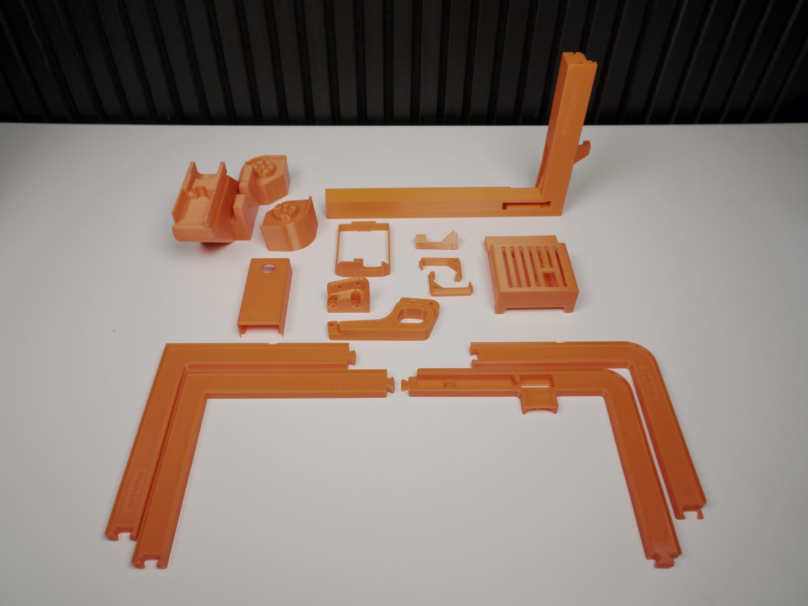
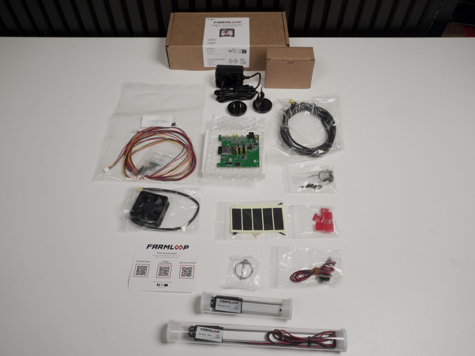
3D-printed parts (orange pieces)
Hardware
- FarmLoop actuators (50 mm & 125 mm)
- ESP32 controller board
- Door-opener button & cables
- Limit switch
- Wiring harness
- Molex cables
- 4-pin-to-6-pin cable - older kits only, see the note below
- External power supply - new kits, replaces the AMS power cabling above
- Stock rubber damper feet
- Double-sided white tape strips
- Black textured tape strips
- Cable ties & wire cutter
Screws & nuts
- M2 × 8 mm (2 pcs)
- M3 × 20 mm (1 pc)
- M4 × 16 mm (1 pc)
- M4 × 20 mm (1 pc)
- M3 hex nut (1 pc)
- M4 hex nut (2 pcs)
1. Assemble the door opener
Section titled “1. Assemble the door opener”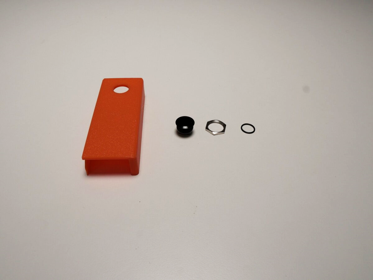
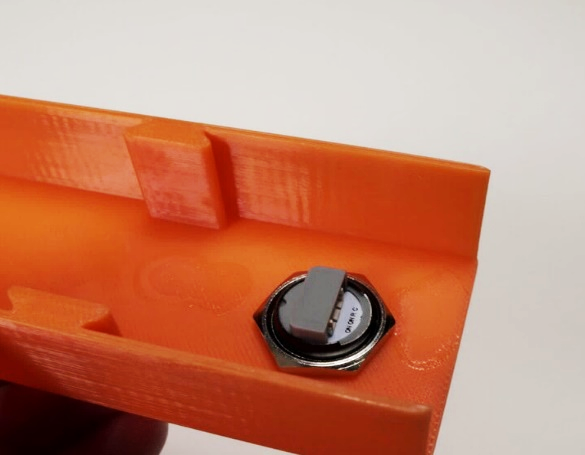
- Push the O-ring over the button until it sits in the recess. Insert the button through the hole in the orange bracket from the top.
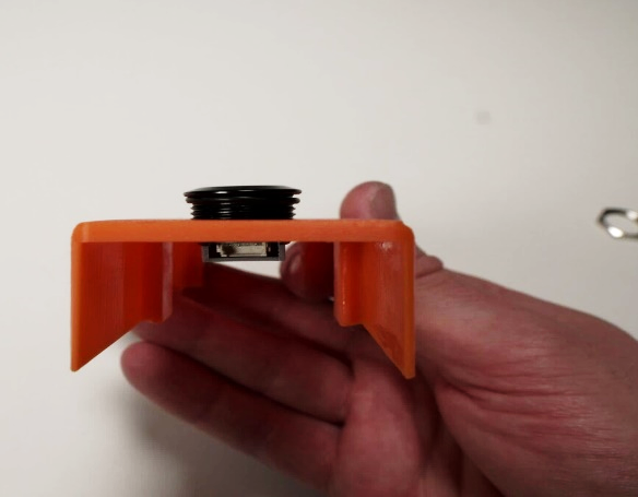
- Secure it underneath with the hex nut.
-
Flip the bracket over to verify the button sits flush. The hex nut should be tight, and the O-ring should provide a seal. Connect the cable to the door-opener button.
-
Press the rubber damper feet into the blind holes. These are the original rubber feet from your Bambu printer - unscrew them from the printer’s base and reuse them here. They provide vibration dampening and ensure a secure grip on the table. The rubber feet should press-fit snugly. Make sure they are fully seated in the recesses.
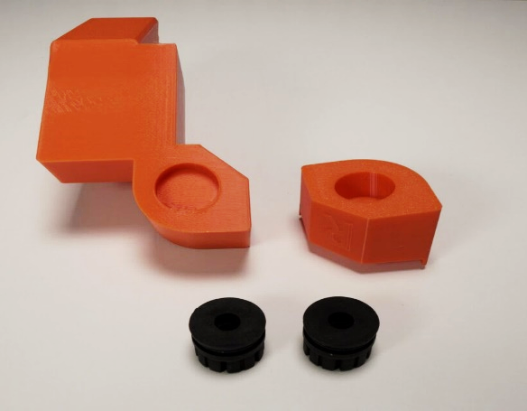
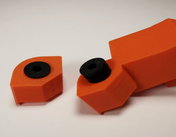
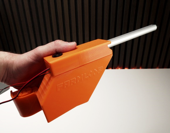
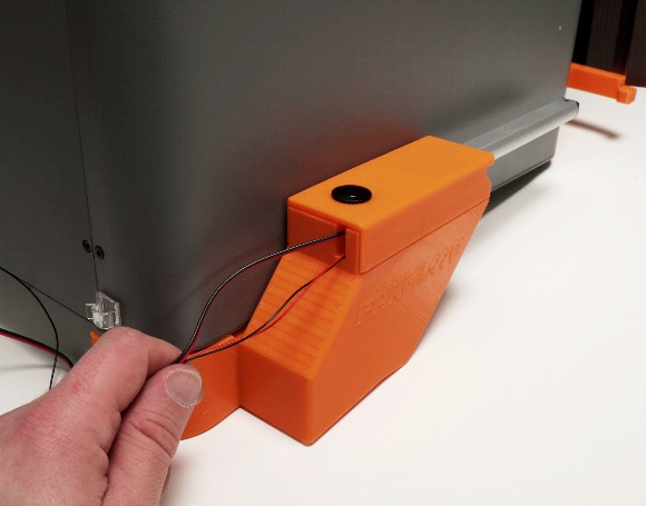
- Install the door actuator and the cover containing the door button into the left tilted foot (marked
L). Mount the feet on the printer.
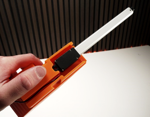
2. Assemble the bender and attach the door hinge bracket
Section titled “2. Assemble the bender and attach the door hinge bracket”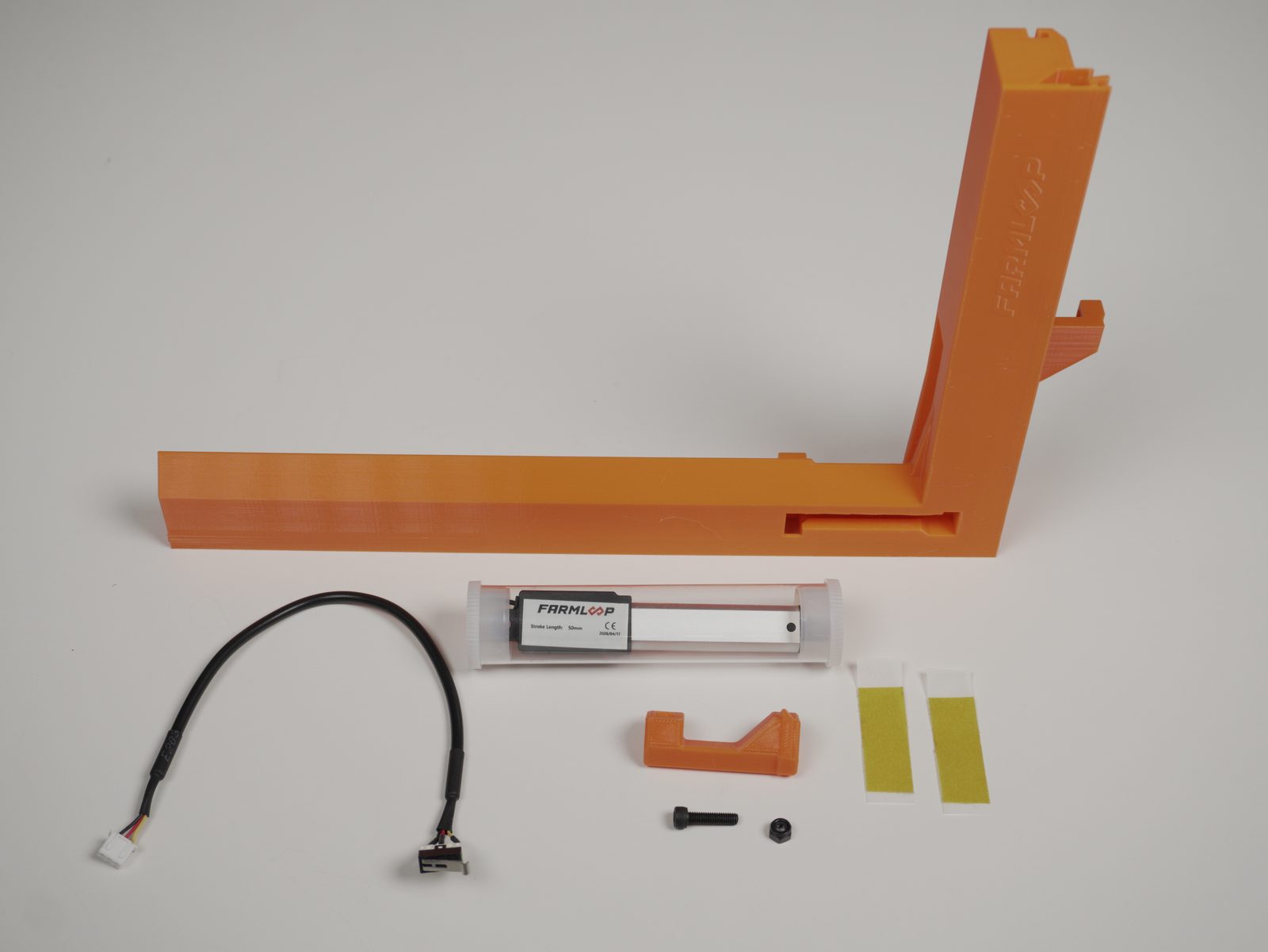
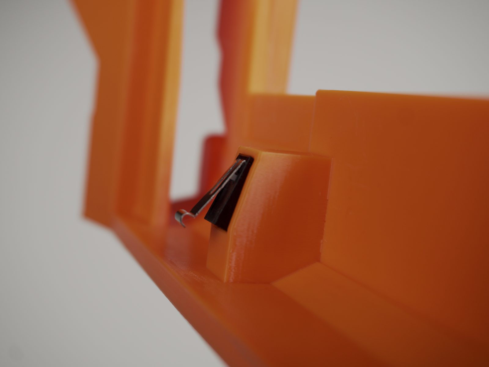
- Insert the limit switch. Make sure the limit switch sits embedded like in the picture.
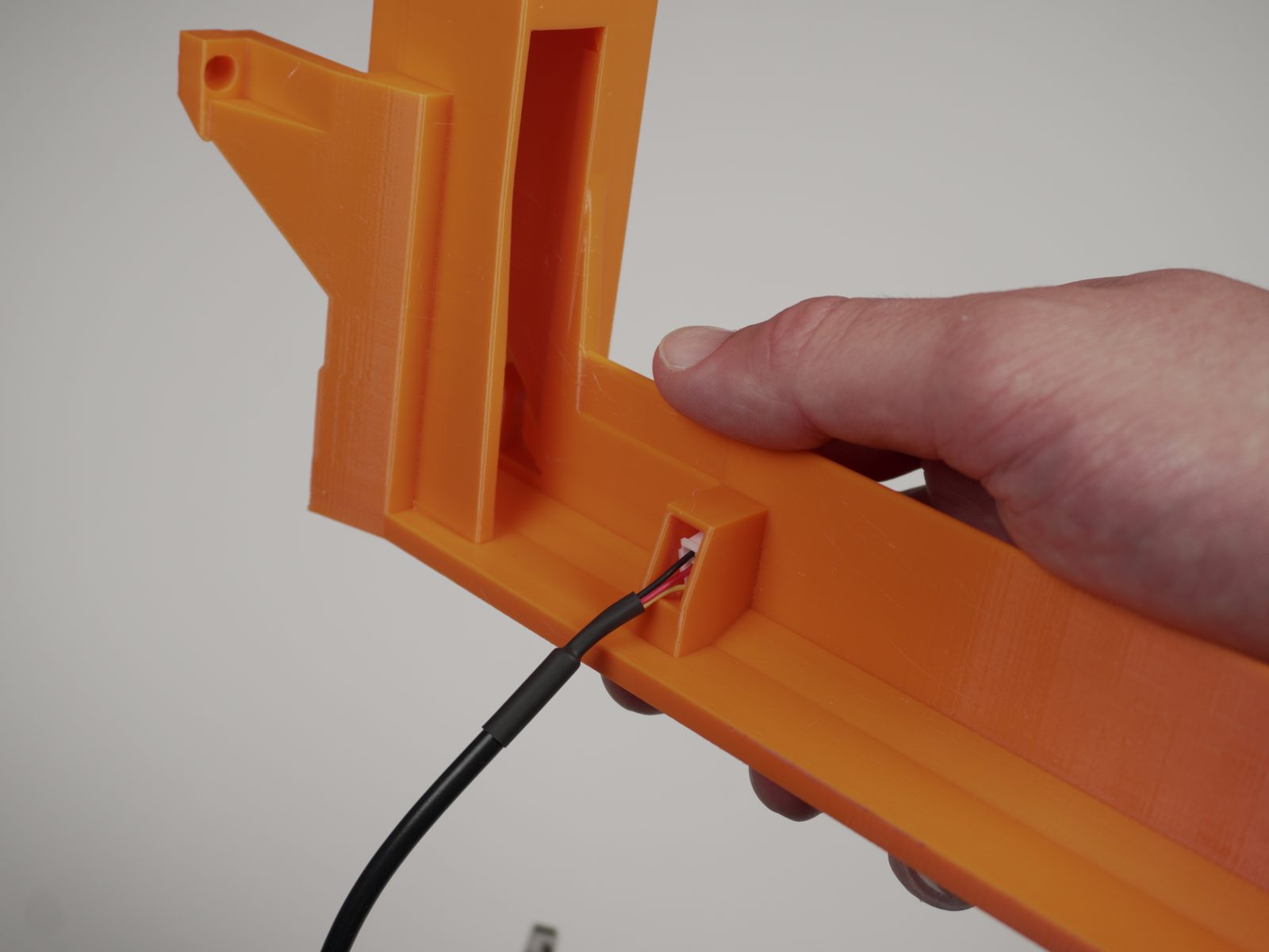
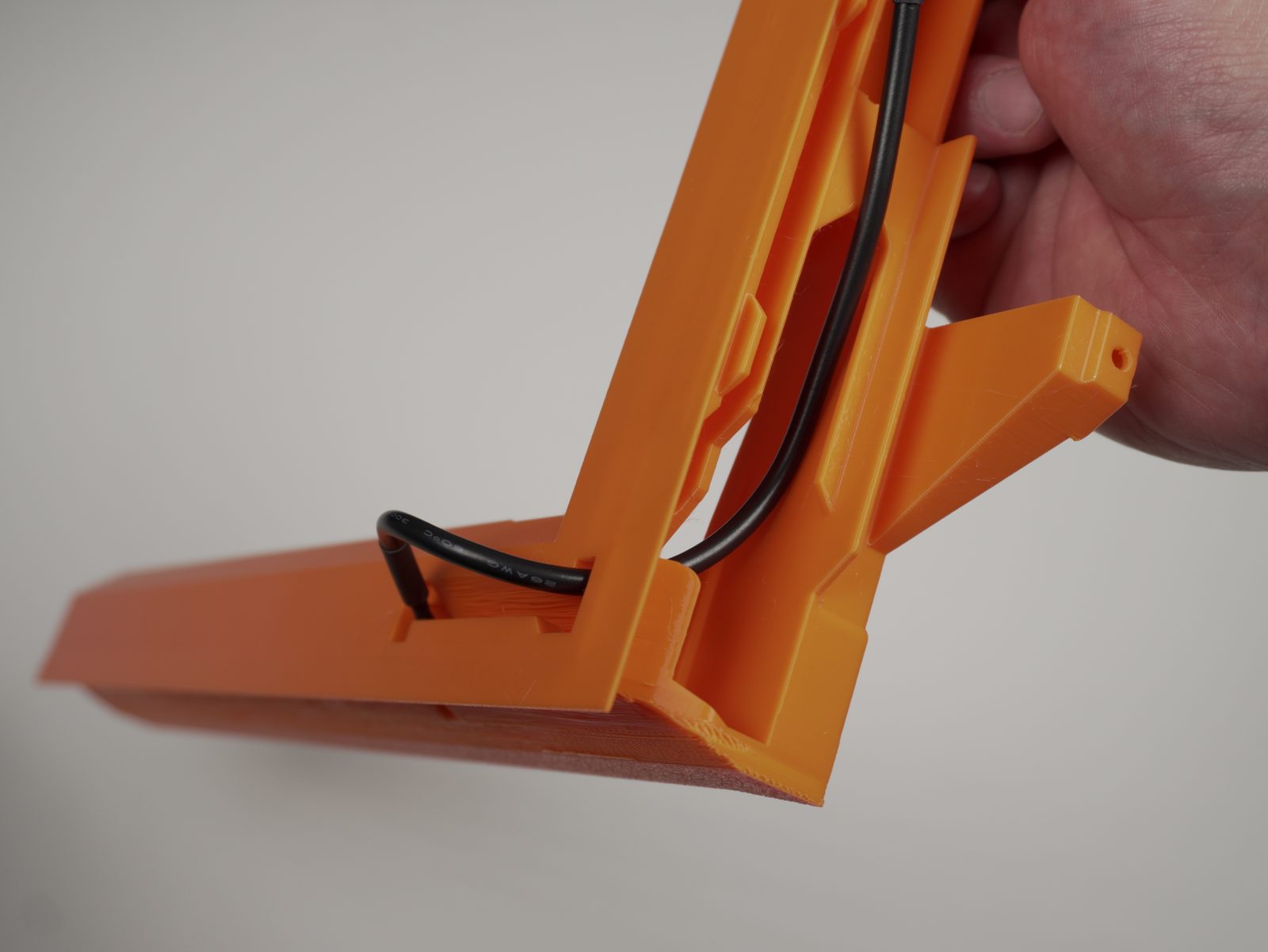
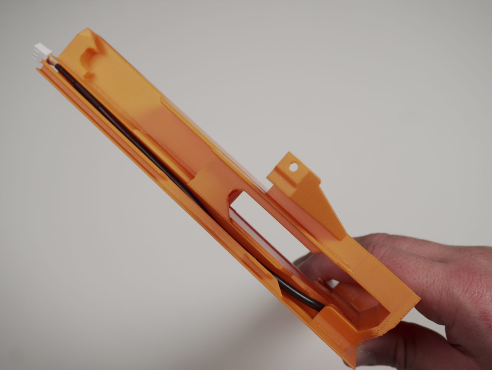
- Route the cables of the limit switch through the bender holder as shown in the pictures.
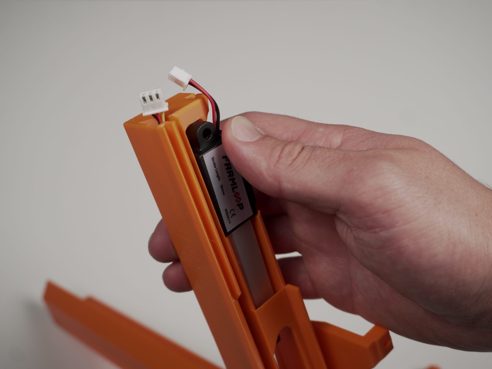
- Insert the Bender actuator.
- Attach the bender hook using the M4 × 16 mm screw and M4 nut.
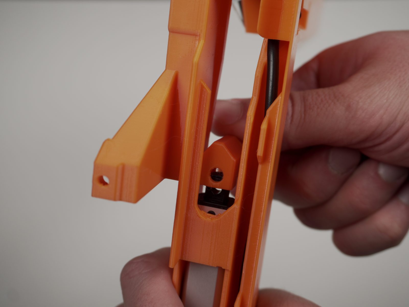
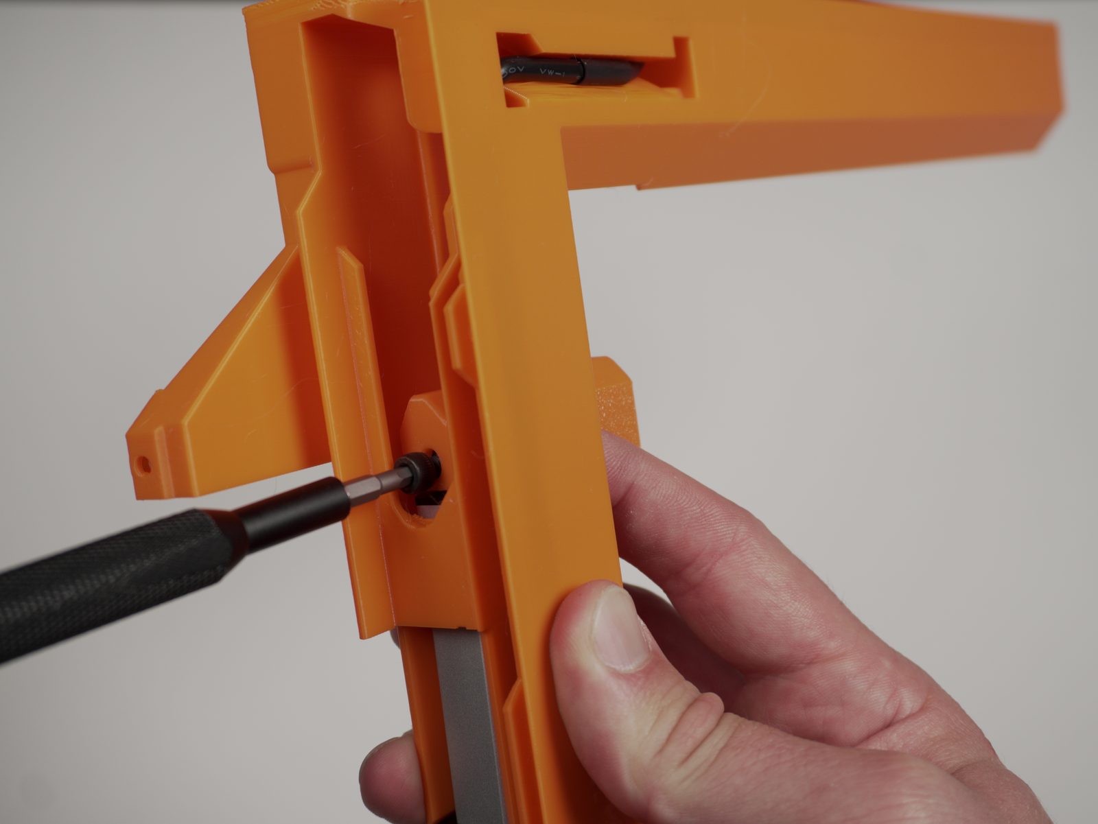
- Finished assembly should look like this.
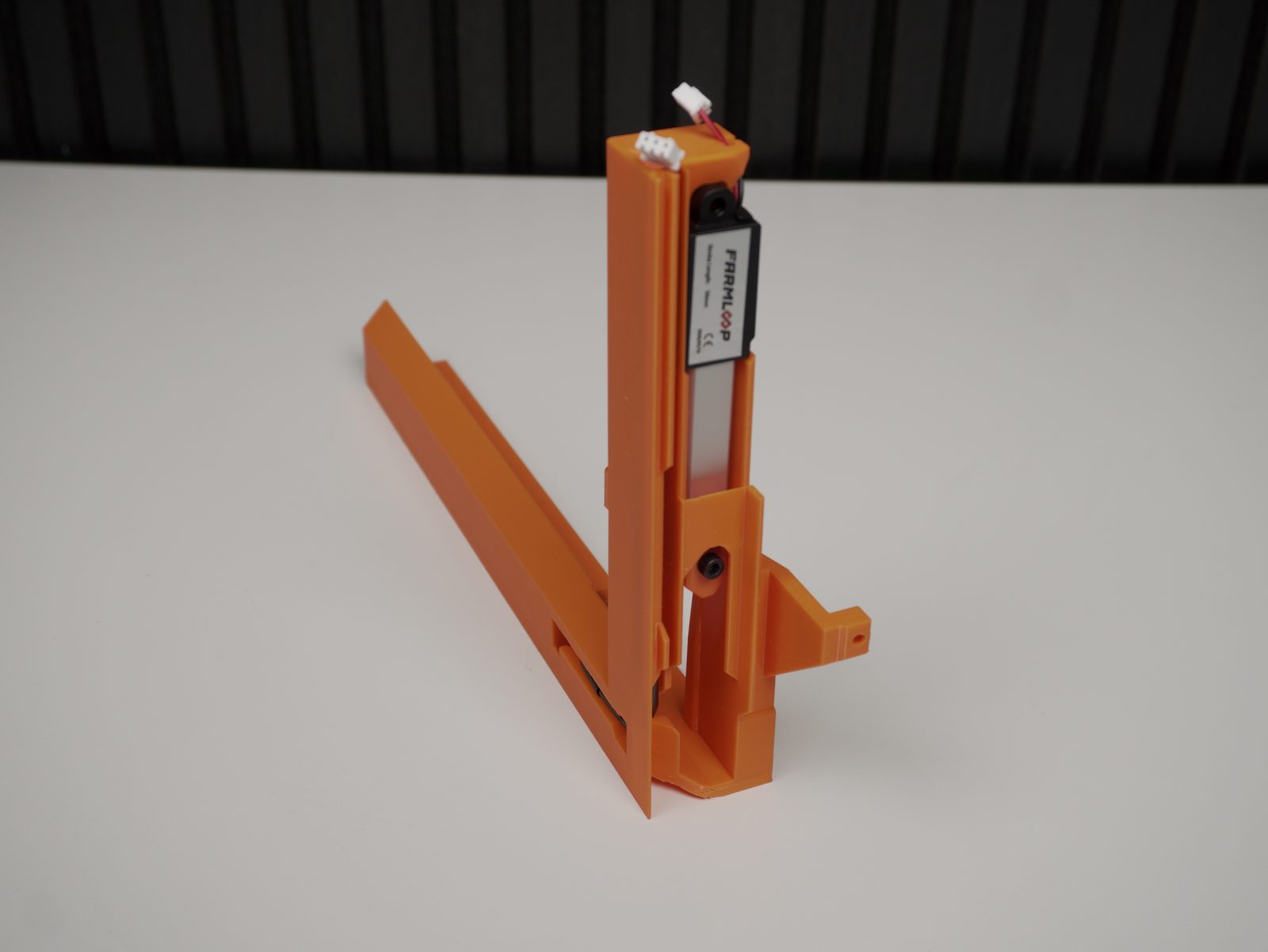
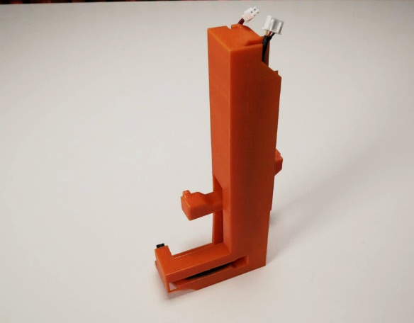
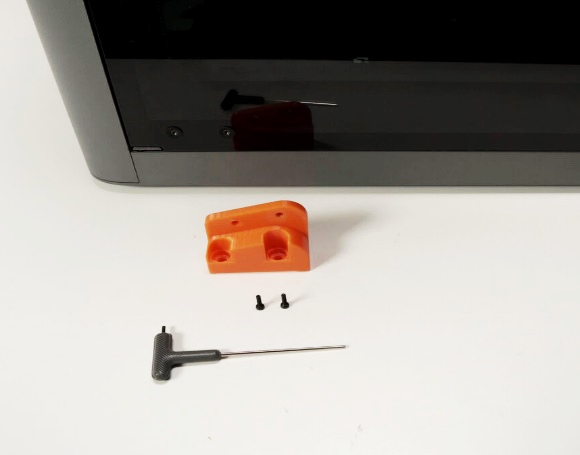
- Remove the two screws on the bottom hinge of the front door.
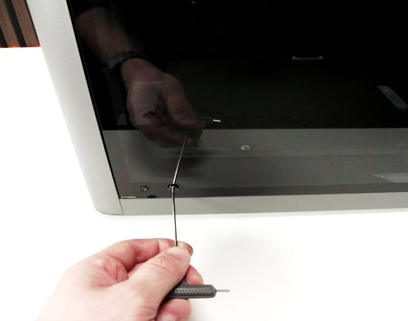
- Attach the front hinge bracket to the printer using the M2 × 8 mm screws.
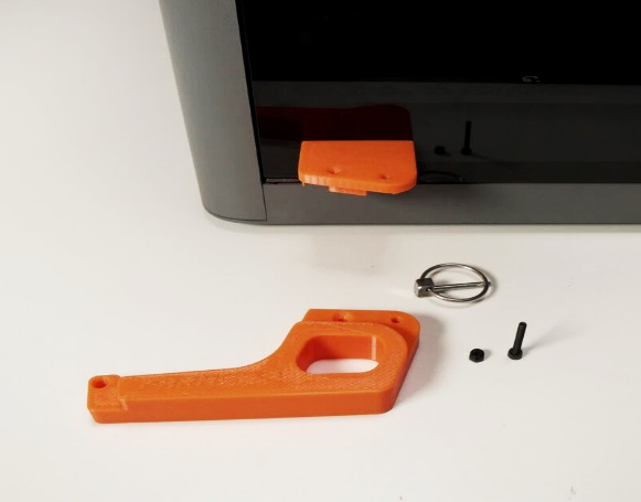
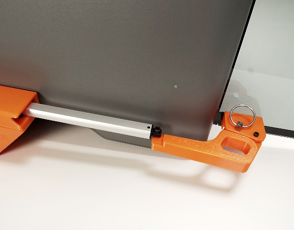
- Position the lid arm onto the front bracket. Secure with the M3 × 20 mm bolt and insert the quick-release pin through the left hole.
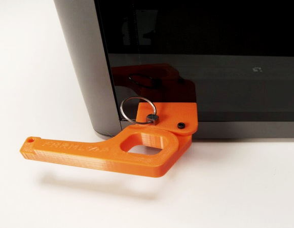
- Attach the actuator to the door bracket with the M4 × 20 mm screw. Do not over-tighten the screw. The joint should still be movable.
3. Install the bender on the printer
Section titled “3. Install the bender on the printer”- Remove the lowest screw on the right side of the printer where the bender will be mounted.
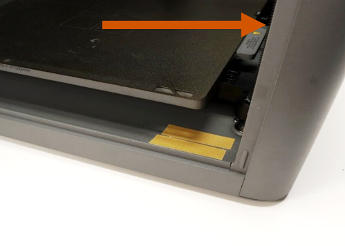
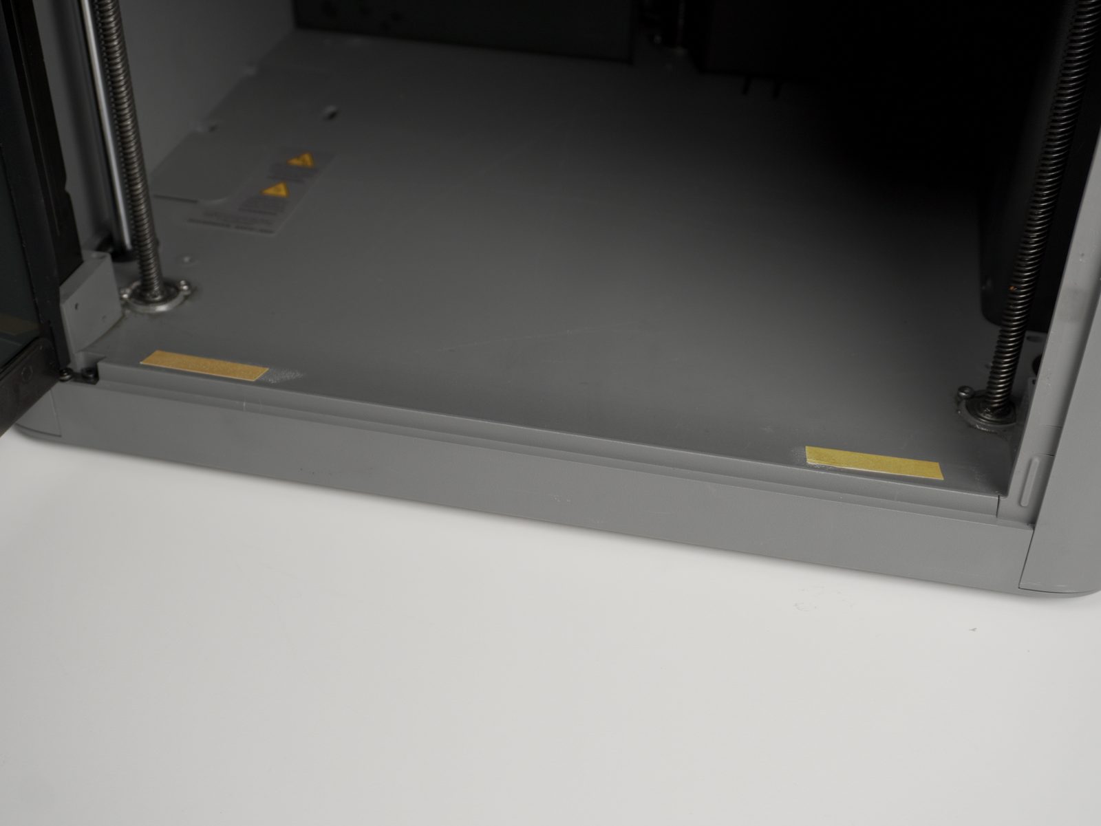
- Apply the included white double-sided tape strips to the front edge of the printer frame.
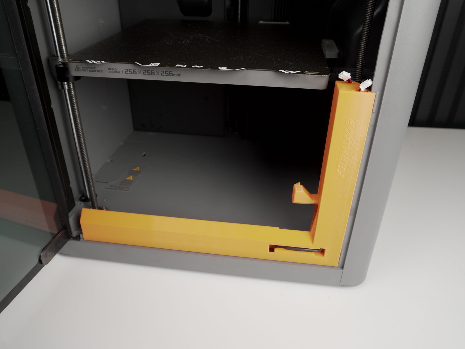
- Insert the bender module. Ensure it does not interfere with Z-axis lead screws or build-plate movement.
- Reinsert the screw behind the bender.
4. Install the PCB
Section titled “4. Install the PCB”- Remove the marked screw.
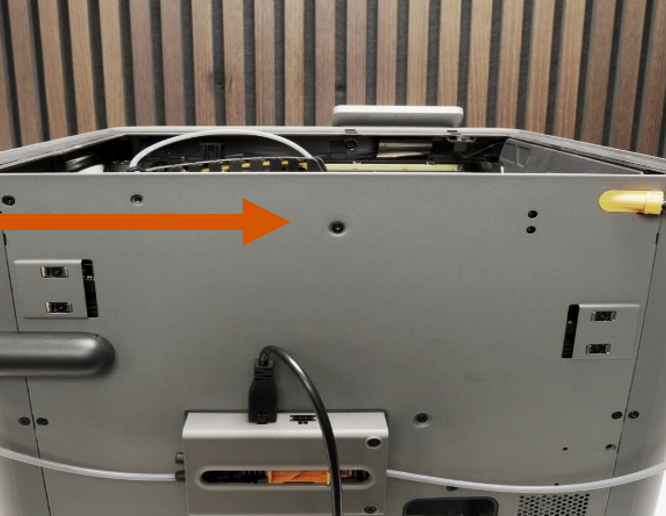
- Place the PCB basket as shown and use the same screw to mount it to the printer.
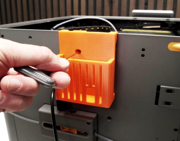
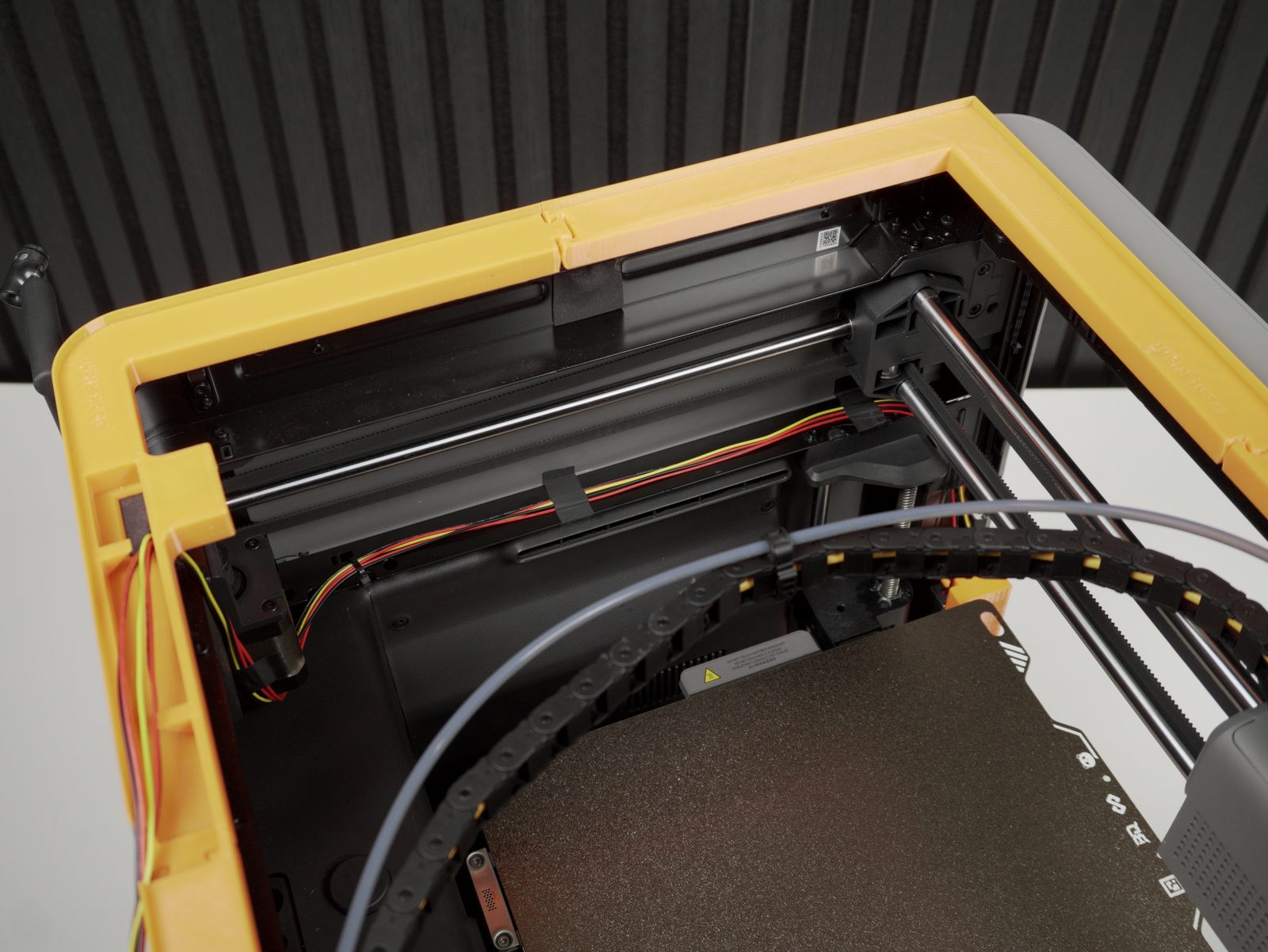
- Assemble and lay the frame on top of the printer.
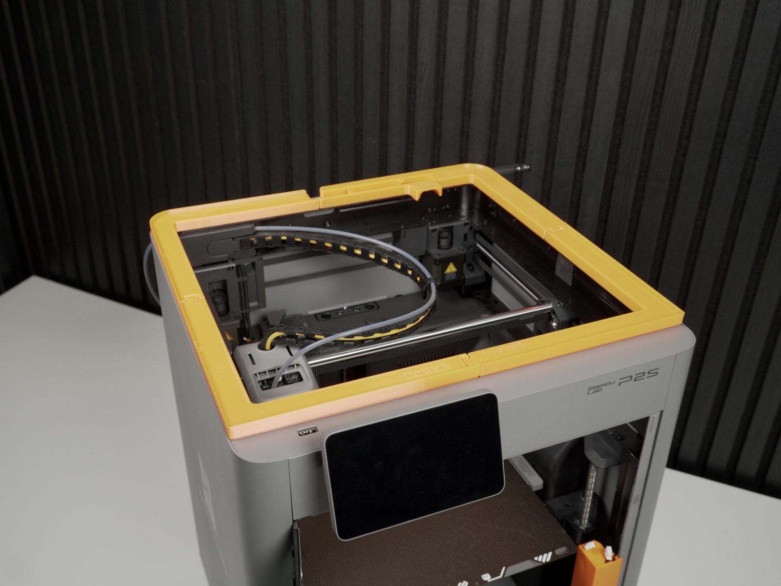
- Connect the cables to the bending assembly.
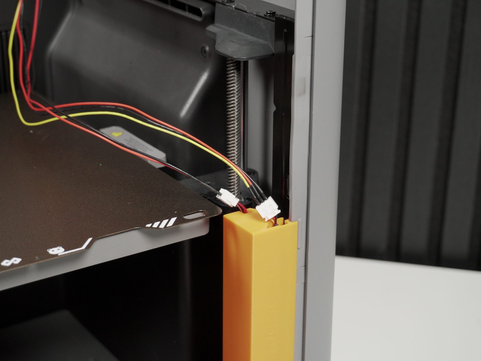
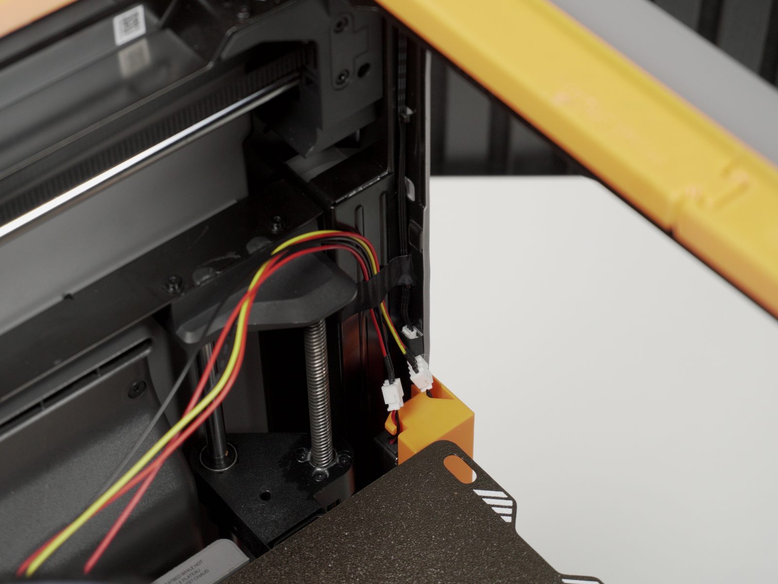
- Pull the cable through the opening and route it through the printer as shown. Secure the cables with tape and cable ties.
5. Cable management and PCB wiring
Section titled “5. Cable management and PCB wiring”

- Connect the cables to the PCB.
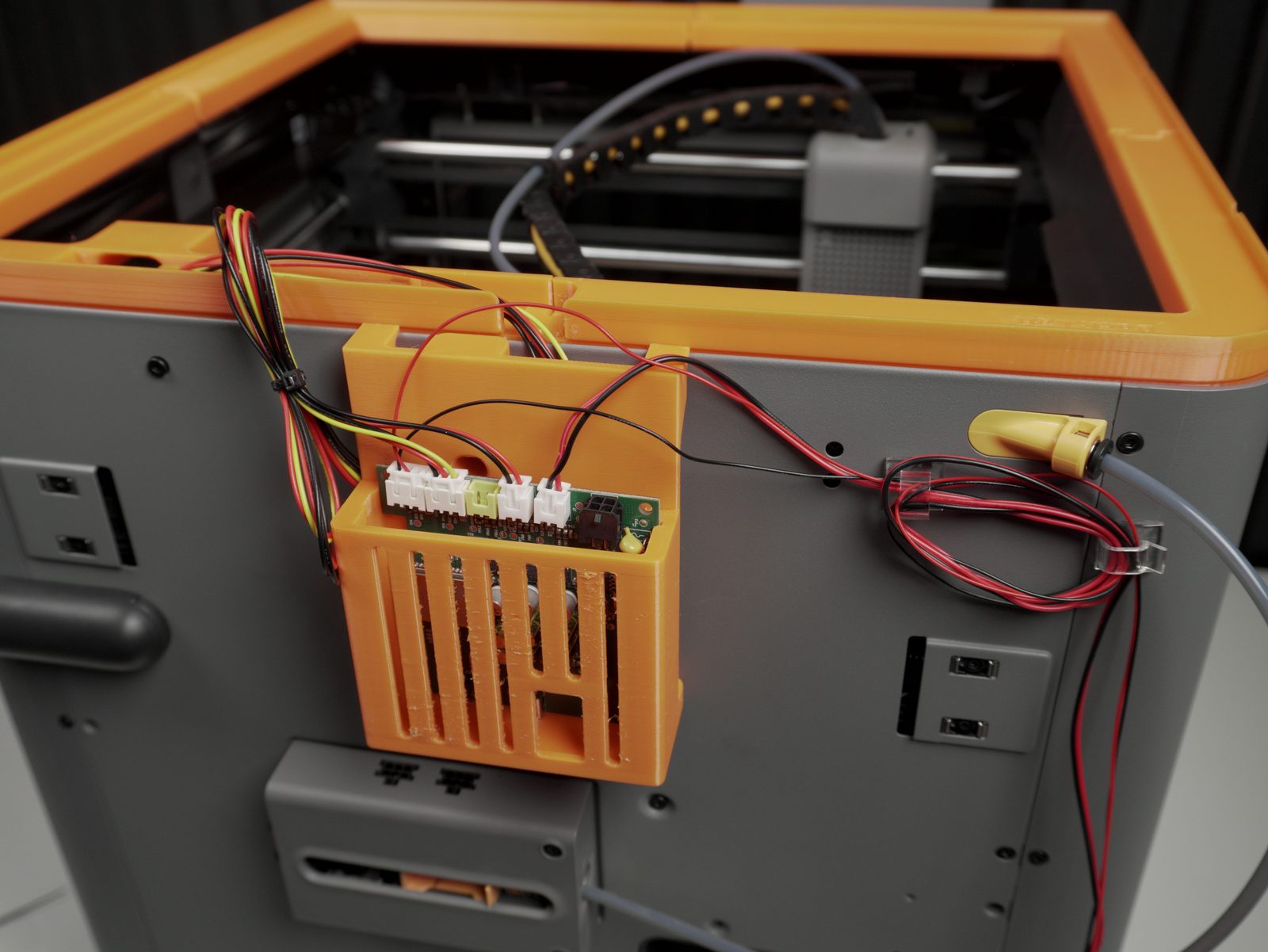
- Connect the power:
- New kits (with external power supply): connect the power supply to the PCB and plug it into a wall socket. The printer’s AMS port is not used at all - skip the AMS cable steps below and leave your AMS wiring untouched.
- Older kits: use the 6-pin-to-4-pin Molex cable to connect the printer and circuit board.
6. Final assembly
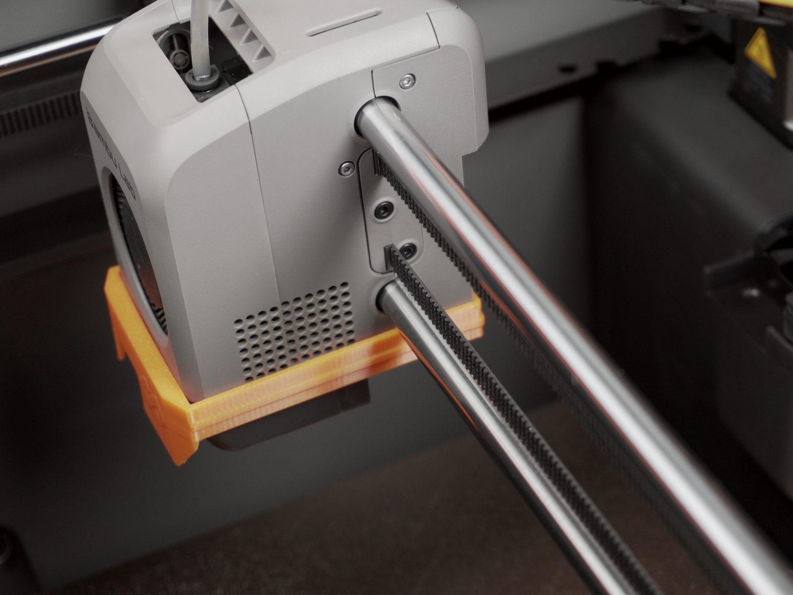
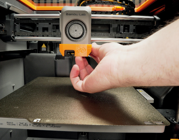
Section titled “6. Final assembly”- Hook the scraper in at the back, then pull the front down over the print head.
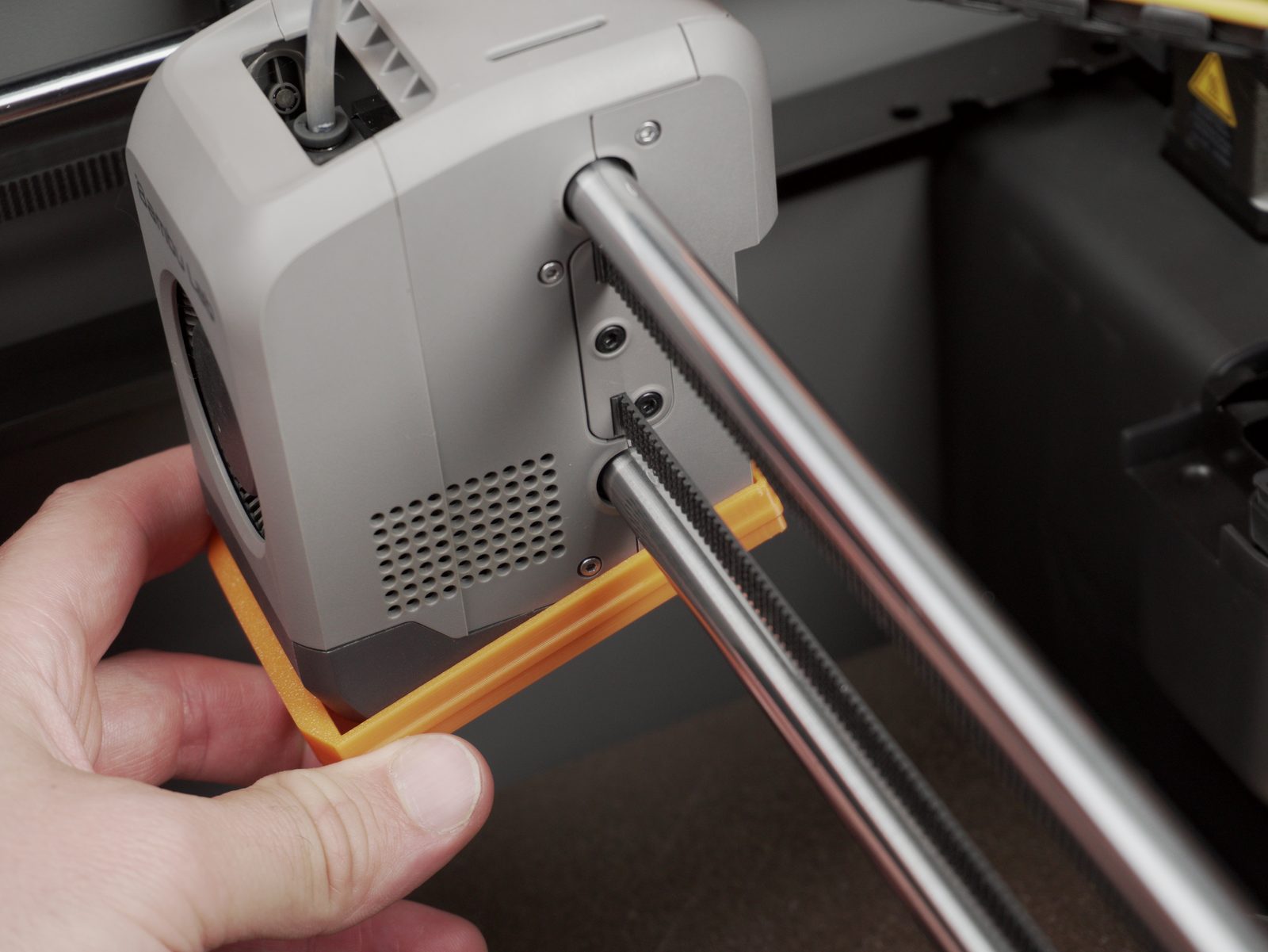
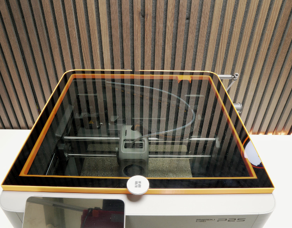
- Insert the top glass into the frame.
Operation
Section titled “Operation”Door-button controls
Section titled “Door-button controls”The DOOR BUTTON is the manual-control button on the automatic door console. Its function depends on the current system state:
| System state | Action | Result |
|---|---|---|
| Idle | Short tap | Door control (open/close toggle) |
| Idle | Long press (3+ seconds) | Enter test mode |
| Any state | 5 quick taps within 3 seconds | Enter OTA configuration mode |
| Reset after safety-check failed | Single tap | Recovers from SAFETY_FAILED state. Homes bender, closes door, returns to initial state. |
OTA mode (firmware updates + trigger-mode setup)
Section titled “OTA mode (firmware updates + trigger-mode setup)”OTA is how you flash new firmware and how you wire up the Digital trigger mode (printer IP + LAN access code). The full walkthrough - entering OTA mode, accessing http://farmloop.local, uploading a .bin file - lives on the Accessing the board (OTA mode). Trigger-mode setup is on the Trigger mode page.
LED signals
Section titled “LED signals”After the board boots, the LED shows a sequence indicating connection status.
Successful startup sequence: 3 quick blinks → 5 slow blinks → 10 fast blinks. If you see all three patterns, the board is fully connected to the printer.
During OTA mode: the LED blinks rapidly at 4 Hz continuously until you exit or the timeout is reached.
| LED pattern | Meaning | Action needed |
|---|---|---|
| 3 quick blinks | Boot successful | None, normal |
| 5 slow blinks | Wi-Fi connected | None, good |
| 10 fast blinks | MQTT printer connected | None, fully operational |
| 2 long blinks | Wi-Fi connection failed | Check SSID and password in OTA |
| 4 long blinks | MQTT connection failed | Check printer IP and access code |
Support
Section titled “Support”Stuck? Reach out:
- Contact: Open a support ticket
- Skool community: skool.com/3dfarmers
- Community (Pro members): log in at app.3d-farmers.com to access the Discord invitation