FarmLoop Stage 2 assembly, Bambu A1
This guide covers installing FarmLoop Stage 2 on the Bambu Lab A1. A1 Mini has its own guide at FarmLoop Stage 2 assembly, Bambu A1 Mini.
Read through the whole guide before you start. Lay out every part so you don’t have to stop mid-install.
Prerequisites
Section titled “Prerequisites”- Bambu Lab A1 with latest firmware installed
- Printed parts from MakerWorld - FarmLoop Stage 2 for A1
- FarmLoop Pro subscription, sign up at app.3d-farmers.com
- Superglue for the scraper assembly, plus gloves, safety glasses, and a paper towel
- A clean, flat work surface
Hardware assembly
Section titled “Hardware assembly”1. Assemble the printed parts
Section titled “1. Assemble the printed parts”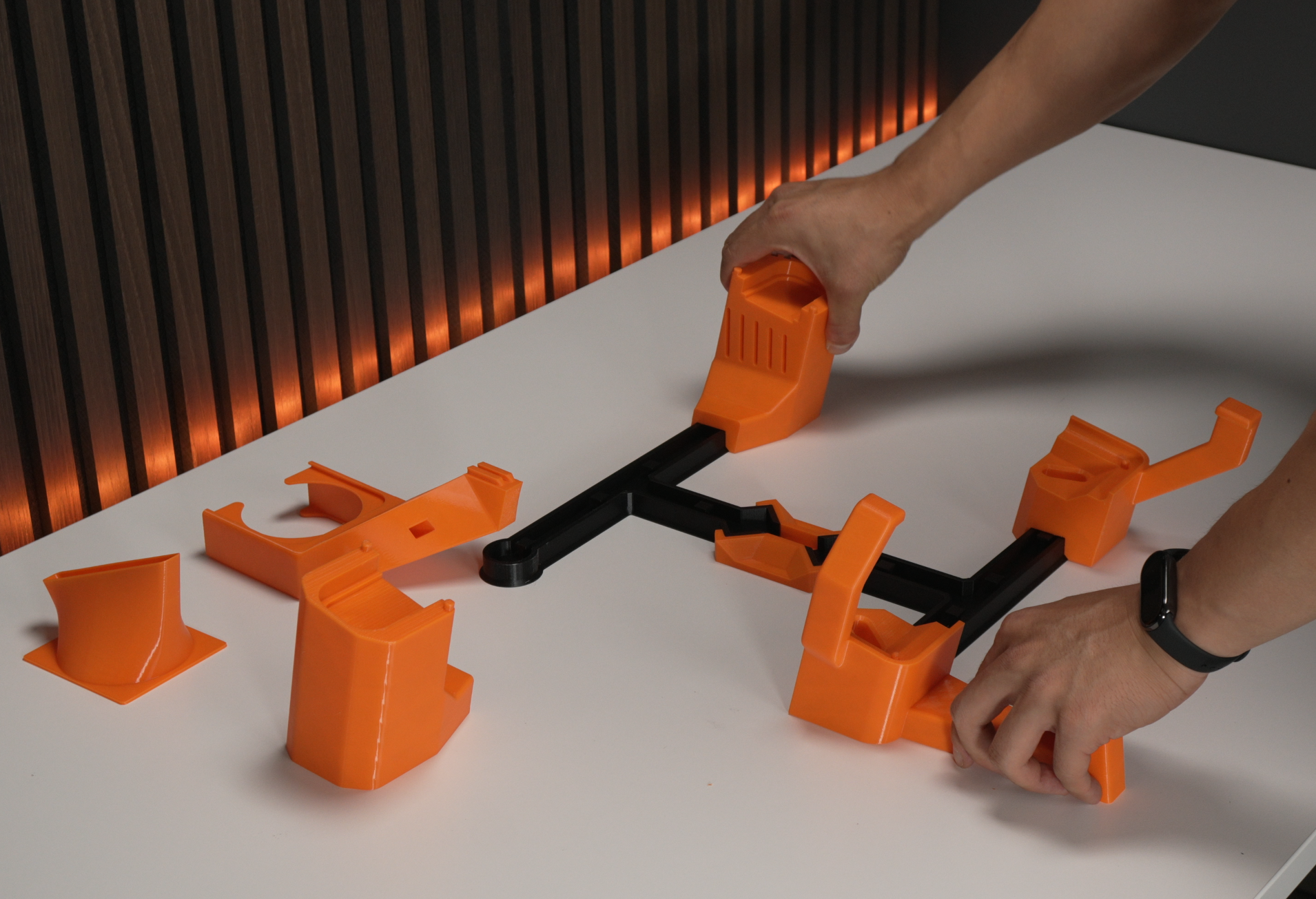
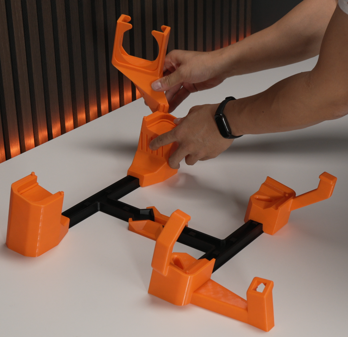
Start by assembling the 3D-printed parts per the orientations shown above.
2. Snap in the linear actuator
Section titled “2. Snap in the linear actuator”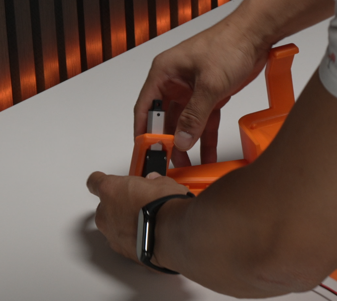
- Black side to the front, sticker side to the back.
- Hide the cable in the cutout channel.
3. Insert the fan
Section titled “3. Insert the fan”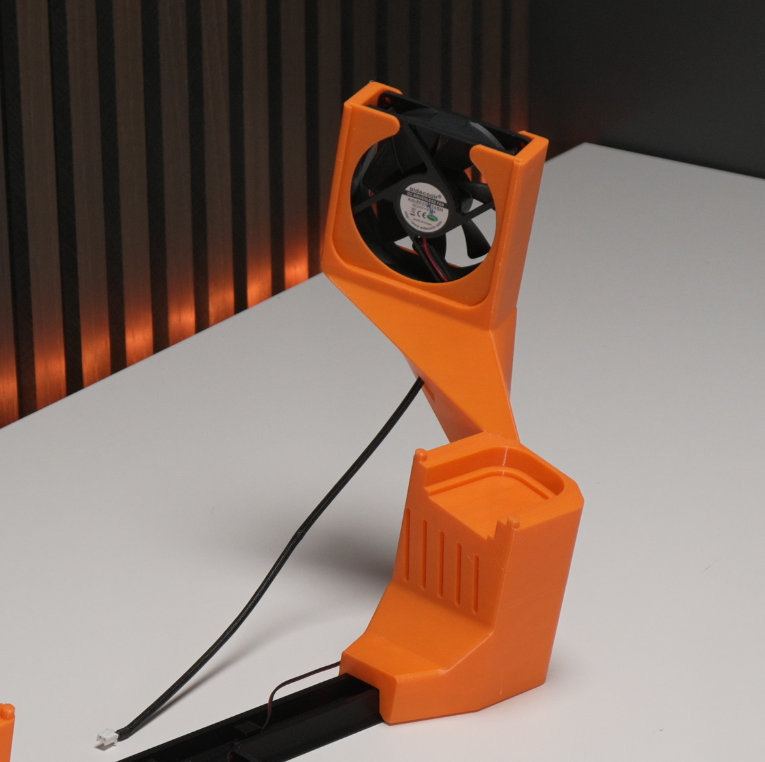
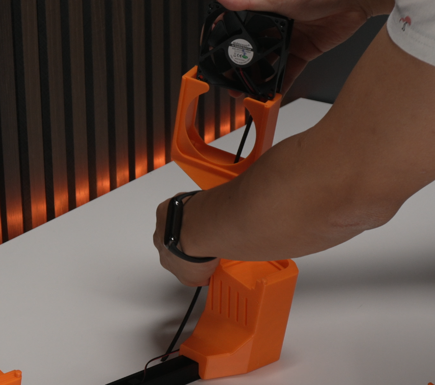
- Insert the fan with the sticker facing the front.
- Feed the cable through the opening for clean cable management.
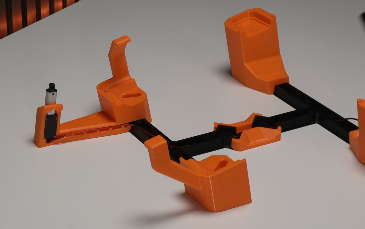
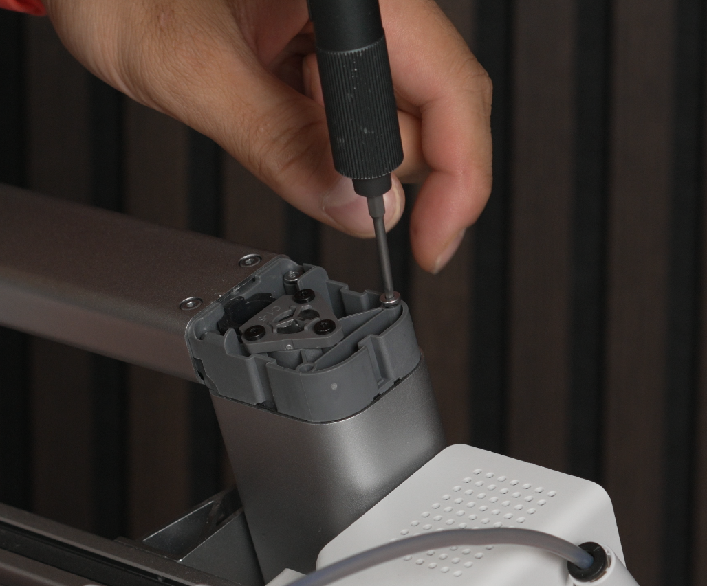
4. Insert the PCB and plug in cables
Section titled “4. Insert the PCB and plug in cables”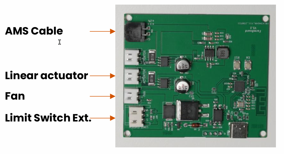
Seat the PCB in its housing, then connect each cable to its labelled port:
- AMS cable
- Linear actuator
- Limit-switch extension
- Fan
5. Add the printer
Section titled “5. Add the printer”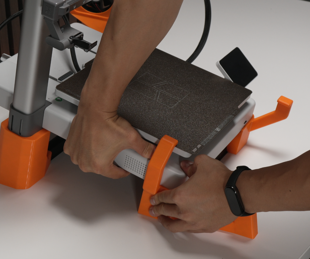
Seat the printer on the tilted base. Make sure the printer sits tightly on the base, wobble here will cause issues later.
6. Install the limit switch
Section titled “6. Install the limit switch”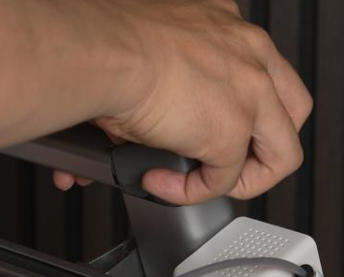
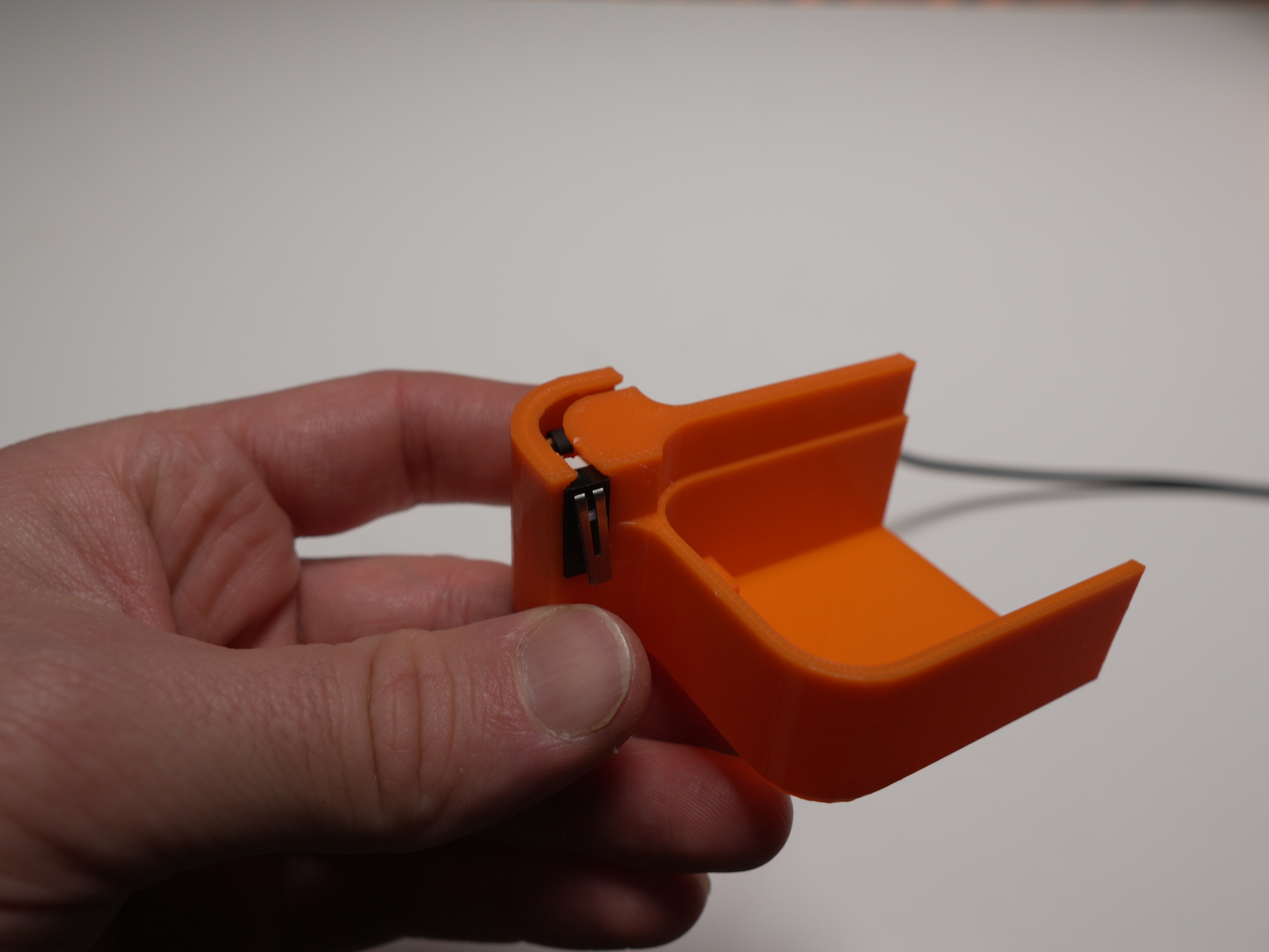
- Remove the grey lid, then remove the two screws underneath.
- Insert the limit switch into the printed holder and connect it to the limit-switch extension cable.
- Mount the assembly using the same two screws you just removed.
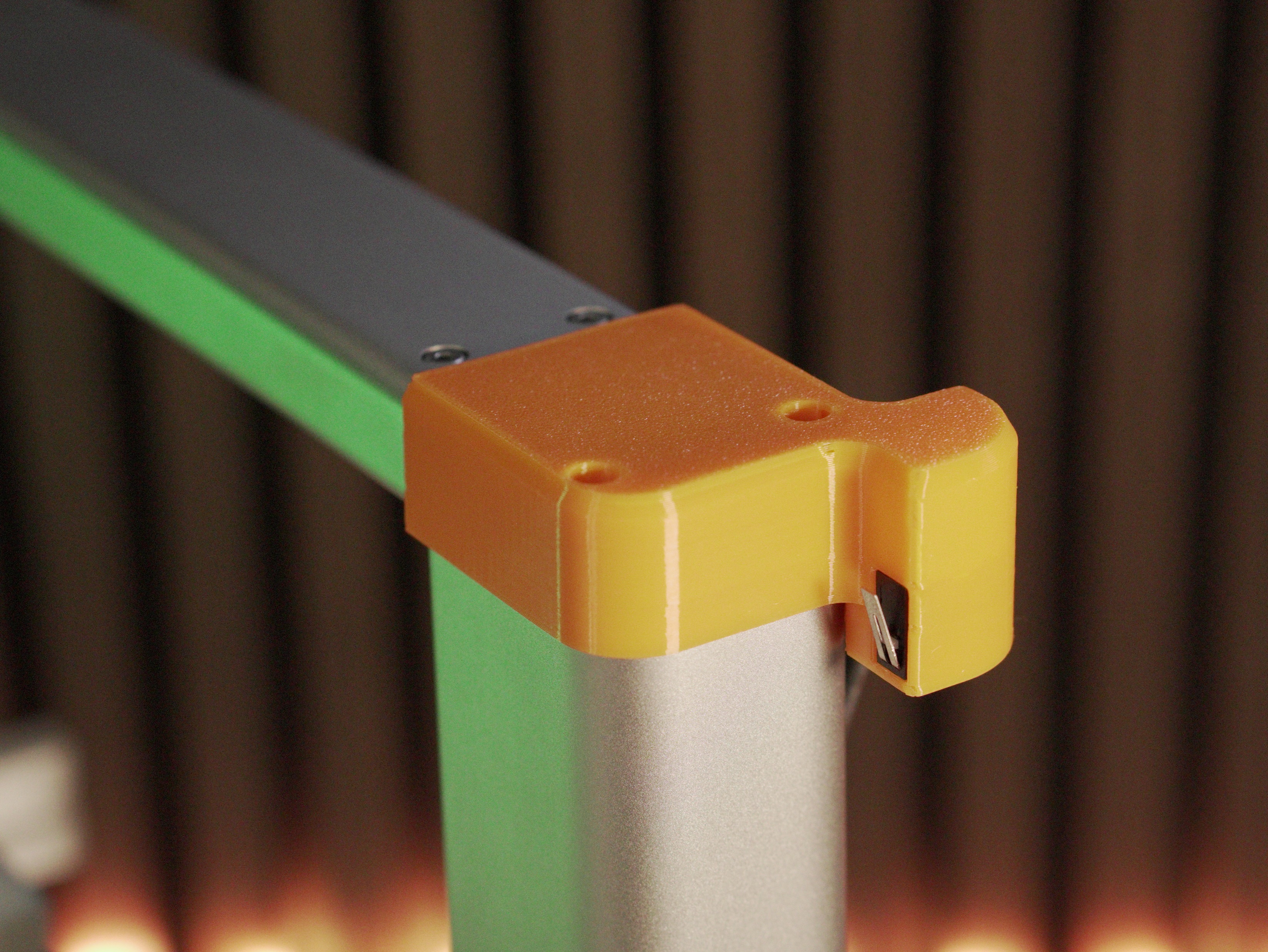
7. Insert the fan duct and connect the AMS cable
Section titled “7. Insert the fan duct and connect the AMS cable”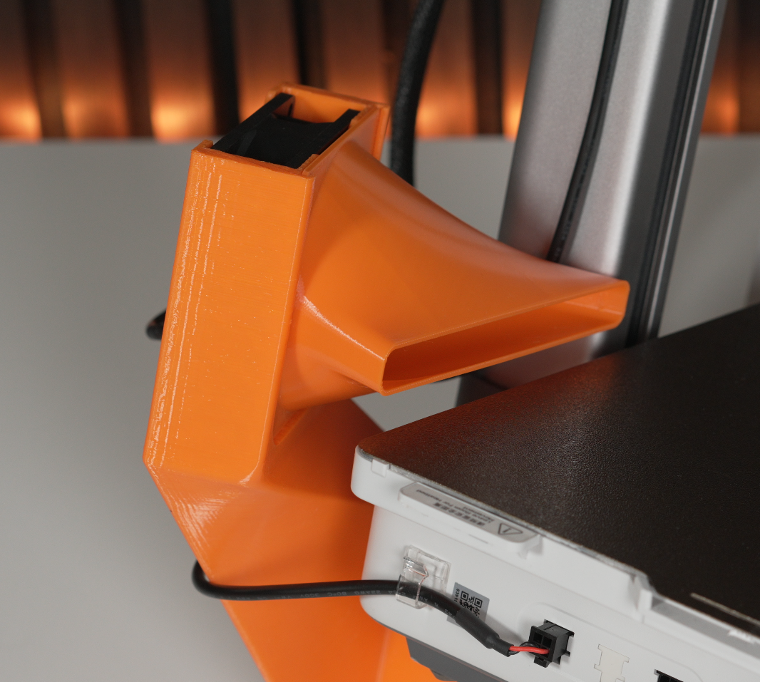
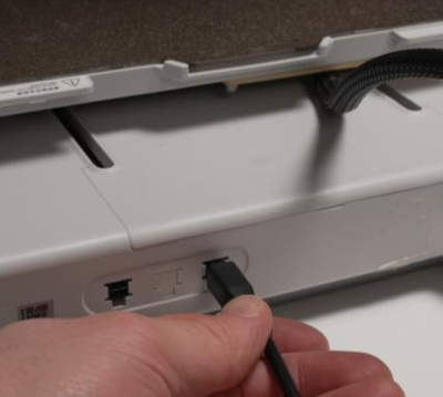
- Slide the fan duct into the slits from above.
- Connect the AMS cable to either of the two ports on the back of the printer.
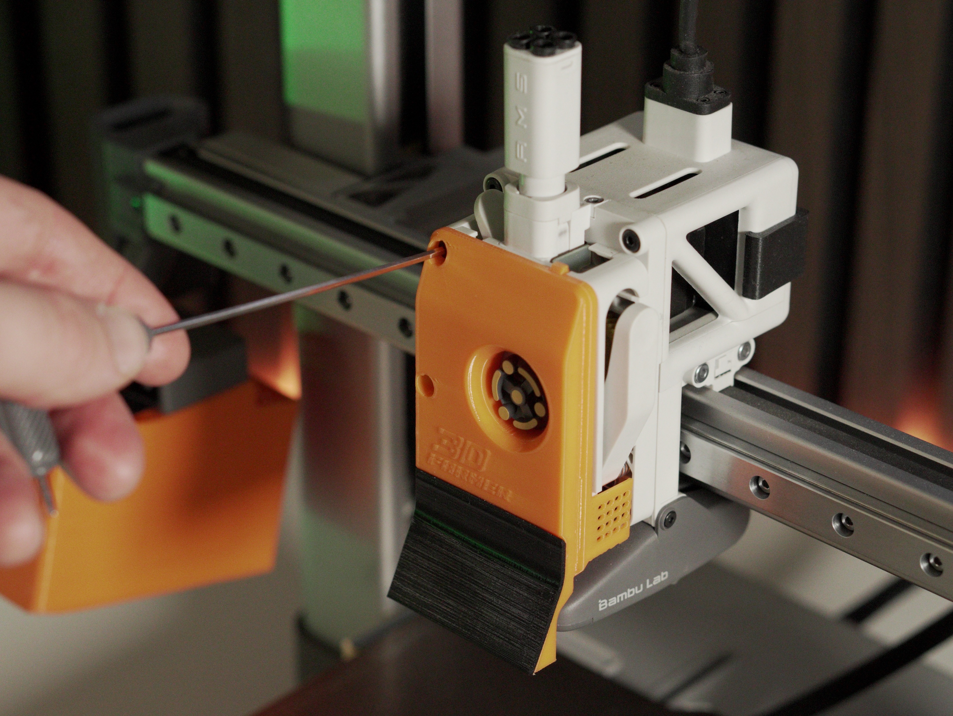
8. Assemble and install the scraper
Section titled “8. Assemble and install the scraper”Start by laying out everything you’ll need:
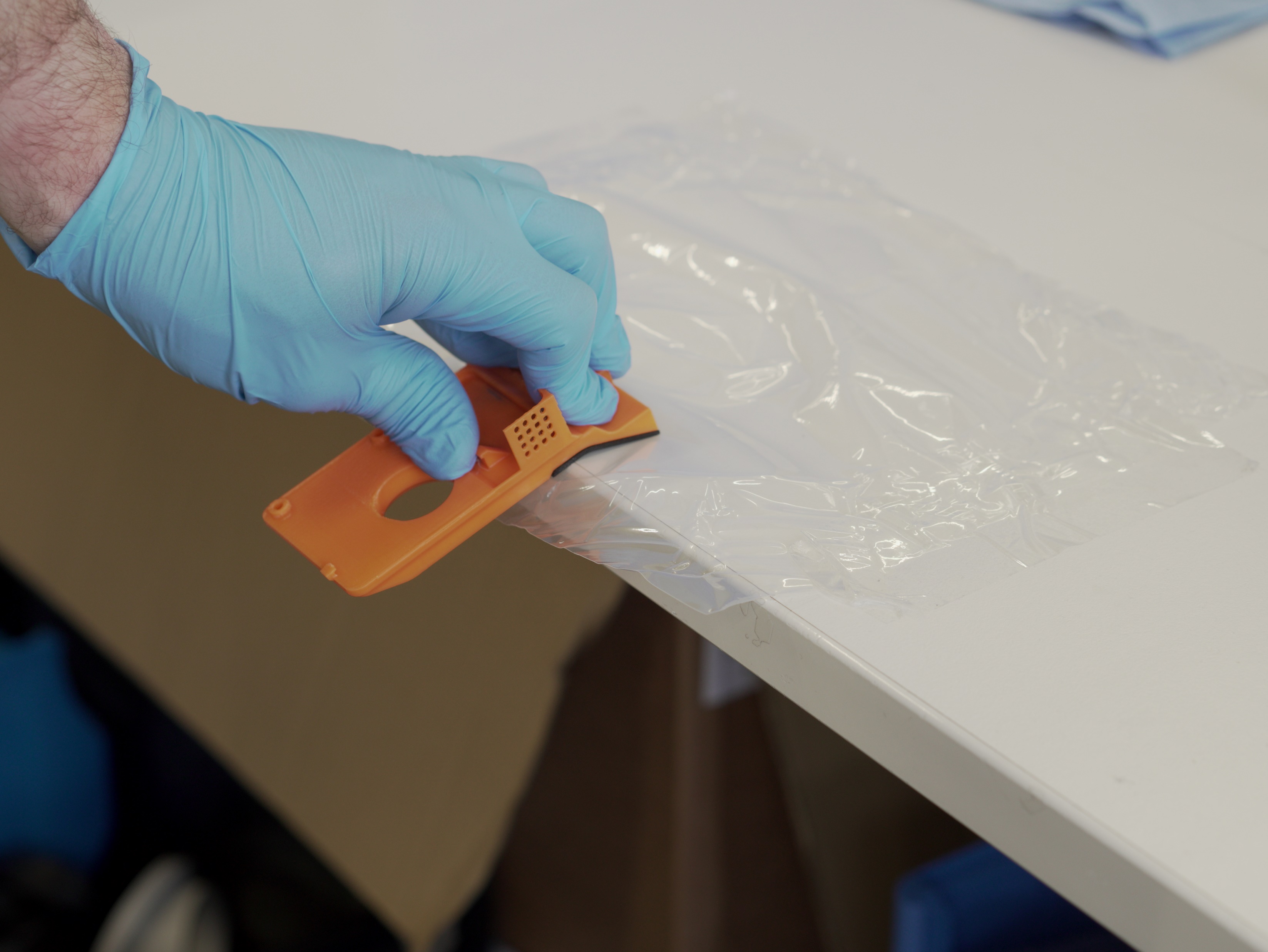
Then glue the TPU and PETG pieces together and let them set:
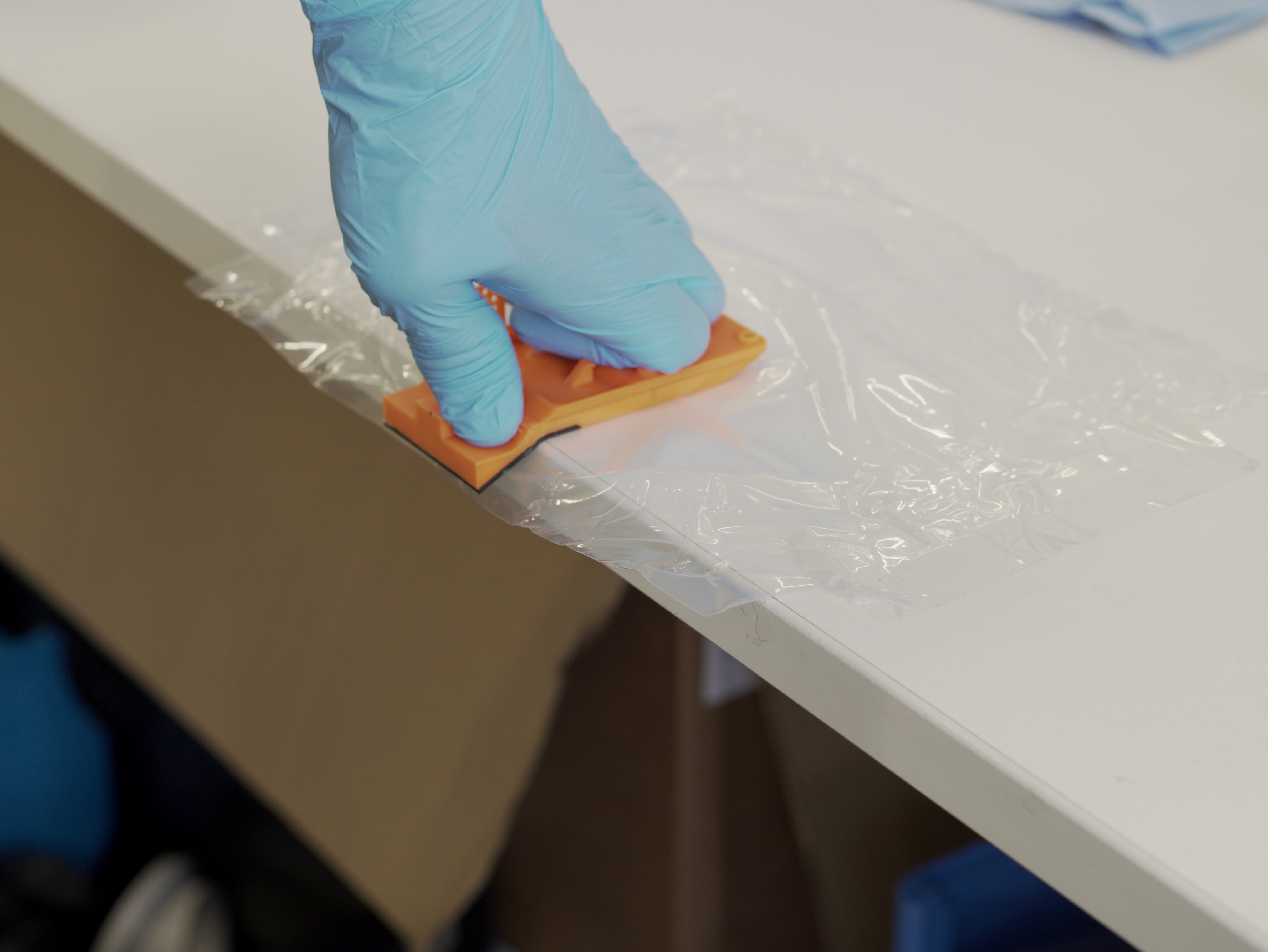
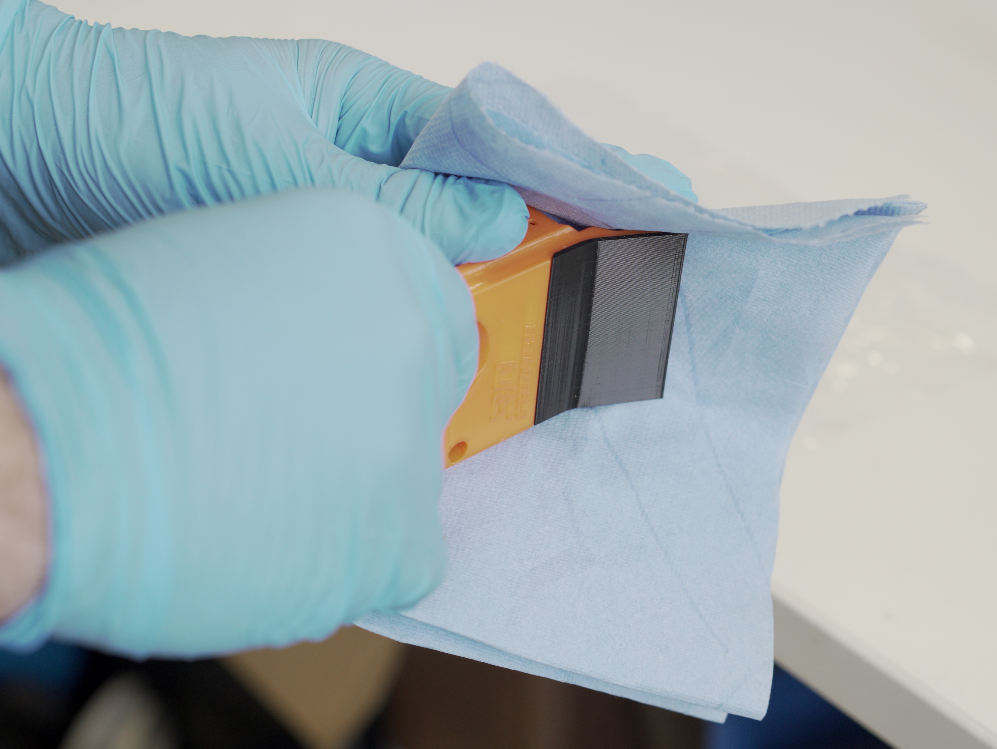
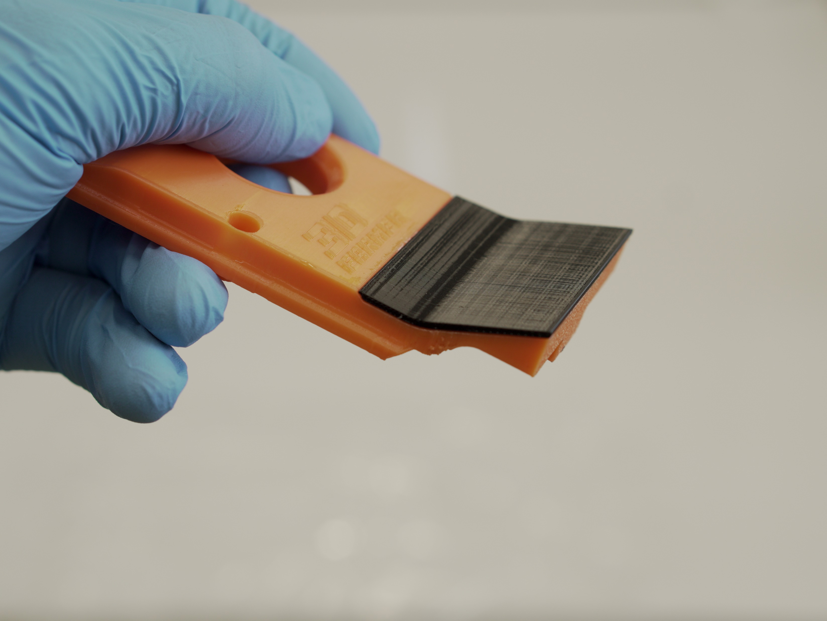

- Glue the TPU part to the PETG scraper part as shown. We recommend superglue.
- Apply glue to the recessed area of the PETG part.
- Press the two parts together on a non-stick surface to prevent them from adhering to the table.
- Wipe away any excess or overflow glue.
- Remove the original cover and the two marked screws.
- Hook the FarmLoop scraper into the top hinges first, then fold it downward.
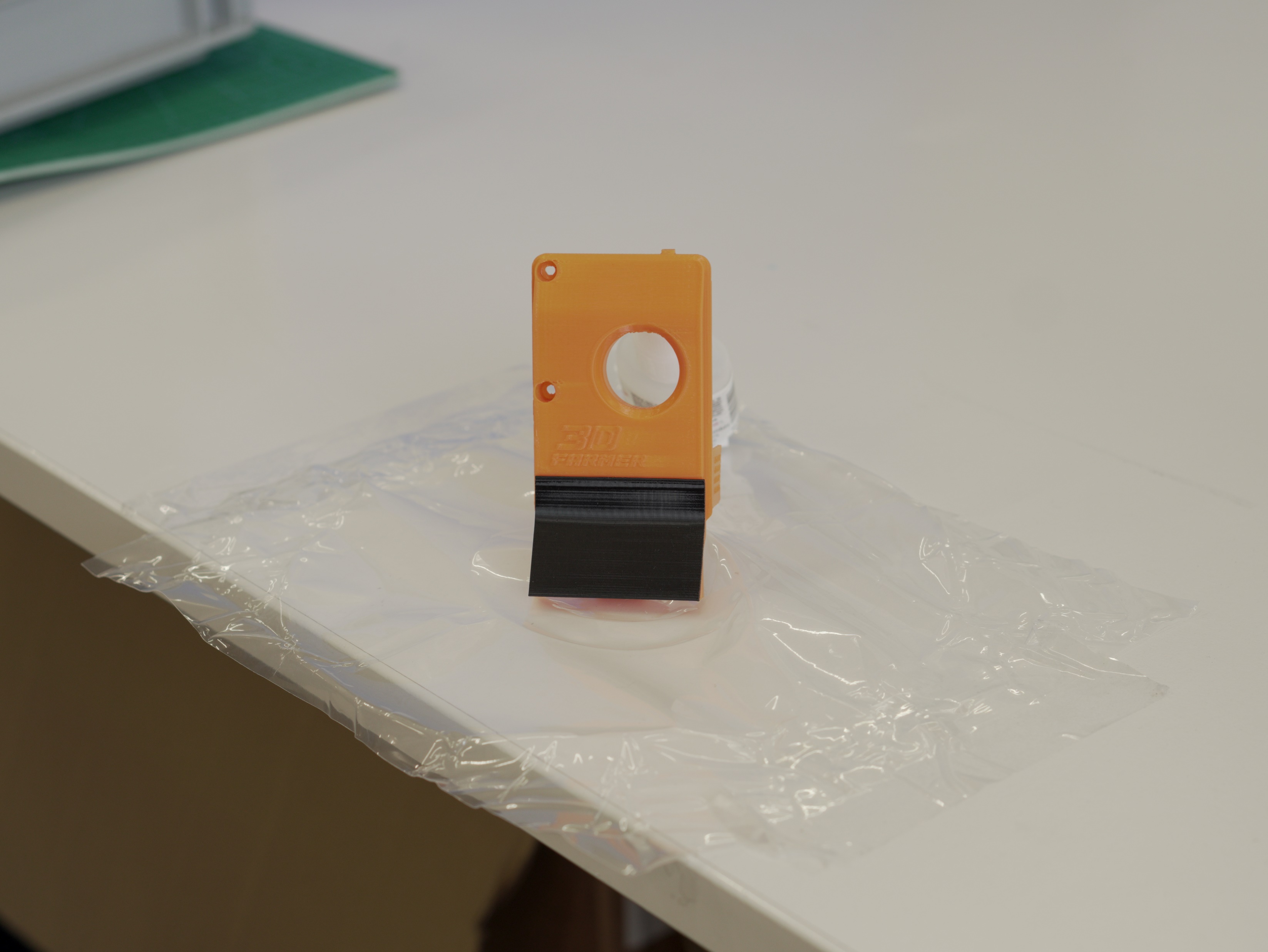
Once the glue has set and the scraper is hooked in, secure it with the screws. The final result should look like this:

We recommend the slightly longer black BT3×8 SHCS (self-tapping) screws for increased strength.
Operation
Section titled “Operation”Limit-switch controls
Section titled “Limit-switch controls”The LIMIT SWITCH on the FarmLoop module is the manual control input. Its function depends on the current system state:
| System state | Action | Result |
|---|---|---|
| Idle | Long press (4-6 seconds) | Fan ON (waits for triple tap) |
| Fan running | Triple tap (3× within 8 s) | Fan OFF + bending cycles start |
| Idle | Double tap (2× within 4 s) | Test mode (fan 2 s + actuator cycle) |
| Any state | Hold > 8 seconds | EMERGENCY STOP, all outputs OFF immediately, returns to idle |
OTA mode
Section titled “OTA mode”OTA is how you flash new firmware and tweak optional settings (bend cycles, actuator travel time, diagnostic counters). The full walkthrough - entering OTA mode, accessing http://farmloop.local, uploading a .bin file - lives on the Accessing the board (OTA mode). Defaults are tuned out of the box, so you only need OTA for firmware updates in most cases.
Configuration parameters
Section titled “Configuration parameters”Settings are saved permanently and persist across reboots.
| Parameter | Description | Range |
|---|---|---|
| Default Bend Cycles | Number of bending cycles per run | 1 – 10 |
| Max Bend Cycles | Maximum allowed bend cycles | 5 – 20 |
| Actuator Travel Time | Time for one full extend or retract | 2000 – 10 000 ms |
| Fan Safety Timeout | Auto-shutoff (built-in) | 2 hours (fixed) |
| Triple-Tap Window | Time window for triple tap | 8 seconds (fixed) |
Troubleshooting
Section titled “Troubleshooting”| Problem | Solution |
|---|---|
| Board does not respond to LIMIT SWITCH | Check limit-switch wiring. Try emergency stop (hold >8 s). If still unresponsive, power-cycle the board. |
| Test mode triggered accidentally | Test mode requires a double tap (2 presses within 4 s). A single tap is ignored. Wait ~12 s for the test to finish and the board returns to idle. |
| Bending starts unexpectedly | Triple tap (3 quick taps within 8 s) starts bending. Hold >8 s for emergency stop. |
| Fan stays on too long | Fan auto-shuts off after 2 hours as a safety measure. To stop earlier, triple-tap to start bending or hold >8 s for emergency stop. |
| OTA mode does not start | OTA needs 5 quick taps (each shorter than 0.8 s) within 3 seconds. Slow taps are not counted. Watch the serial monitor for tap-count feedback. |
| Cannot access OTA page | Ensure you’re connected to the FarmLoop Wi-Fi (password 3D-Farmers). Try http://192.168.4.1 if farmloop.local doesn’t resolve. |
| OTA times out | OTA mode has a 5-minute timeout. Re-enter OTA mode (5 quick taps) and save changes promptly. |
| Settings reset after reboot | Click Save Configuration on the OTA page after changing values. Use Exit OTA Mode (or wait for the timeout) to apply. |
Support
Section titled “Support”- Contact: Open a support ticket
- Skool community: skool.com/3dfarmers
- Community (Pro members): log in at app.3d-farmers.com to access the Discord server