
FarmLoop Stage 2 assembly, Bambu H2D
Read through the entire guide before you start. Have every part from the kit laid out where you can reach it, and make sure the printer is powered off and unplugged before opening anything.
Approximate time: 45-60 minutes.
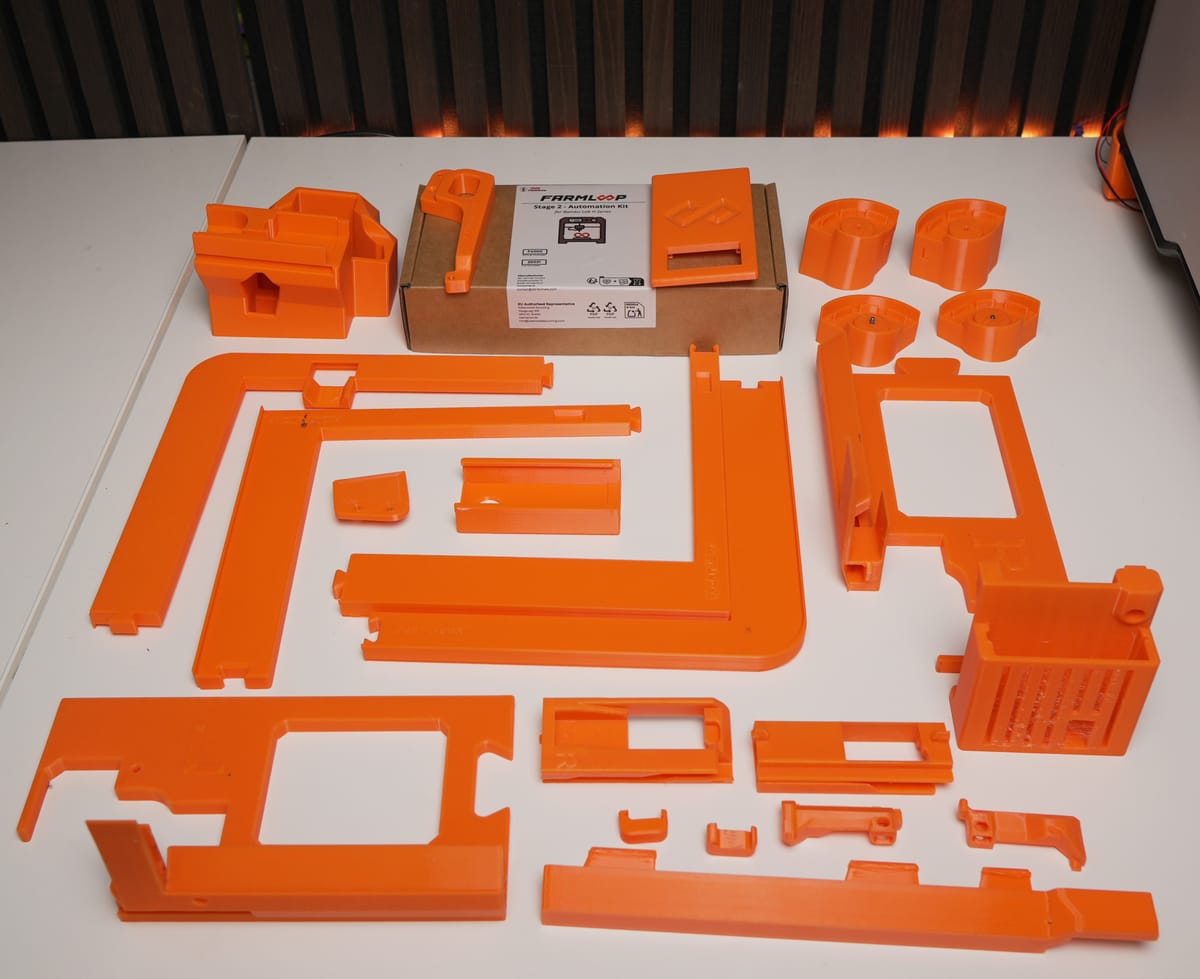
Prerequisites
Section titled “Prerequisites”- Bambu Lab H2D with latest firmware installed
- FarmLoop Stage 2 kit (door-opener parts, bender ×2, wire harness, PCB holder, scraper, tilted feet, lid lifter, screws)
- Printed parts from Makerworld
- FarmLoop Pro App subscription, sign up at app.3d-farmers.com
- A clean, flat work surface large enough to lay every part out
- ~45-60 minutes uninterrupted
1. Assemble the door opener
Section titled “1. Assemble the door opener”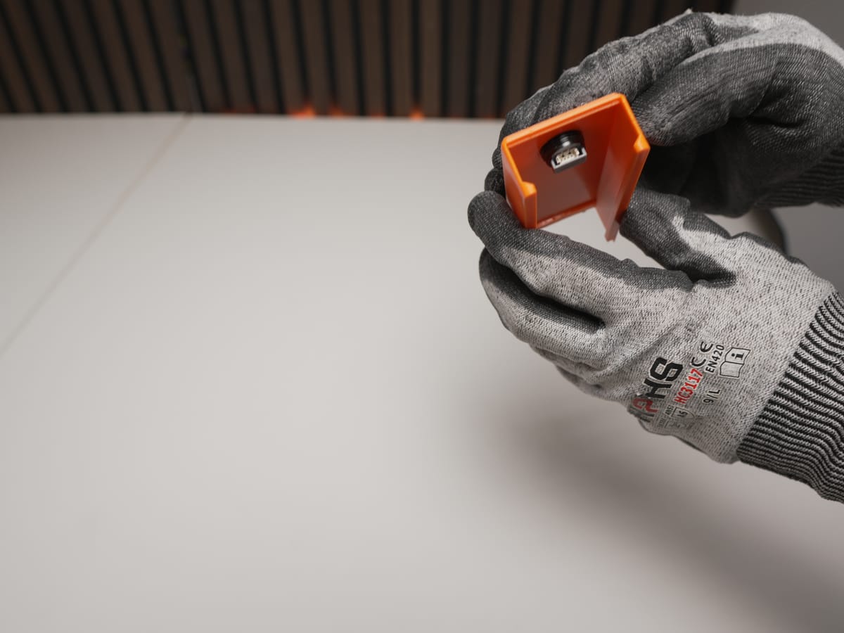
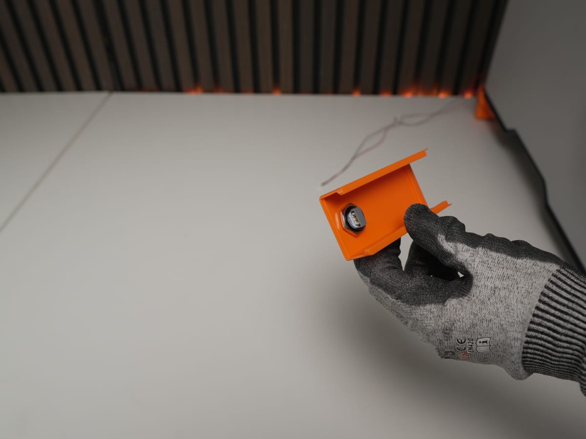
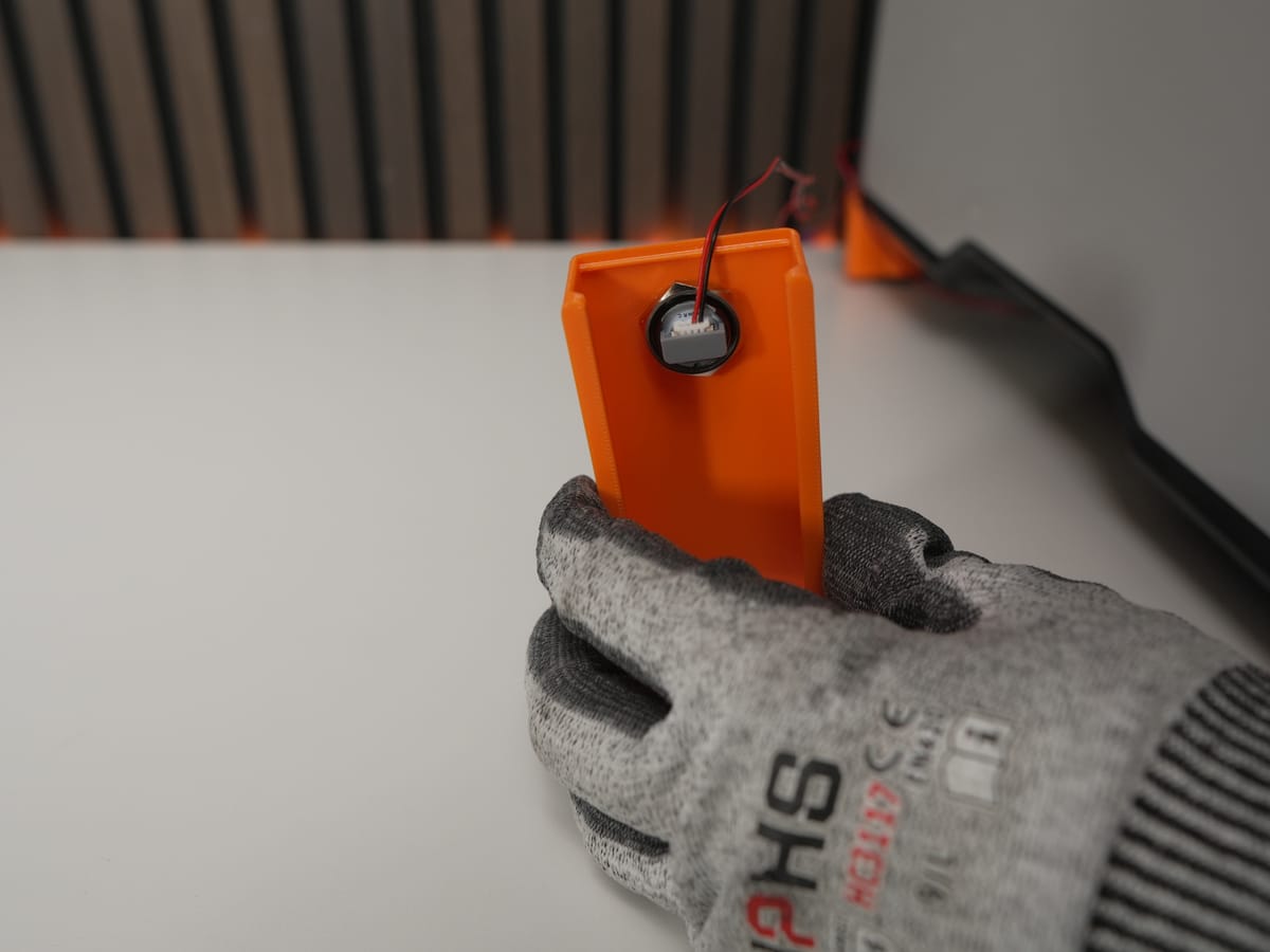
- Press the button into the designated hole in the lid.
- Fix the button using the rubber ring and metal ring.
- Attach both wires to the button terminals.
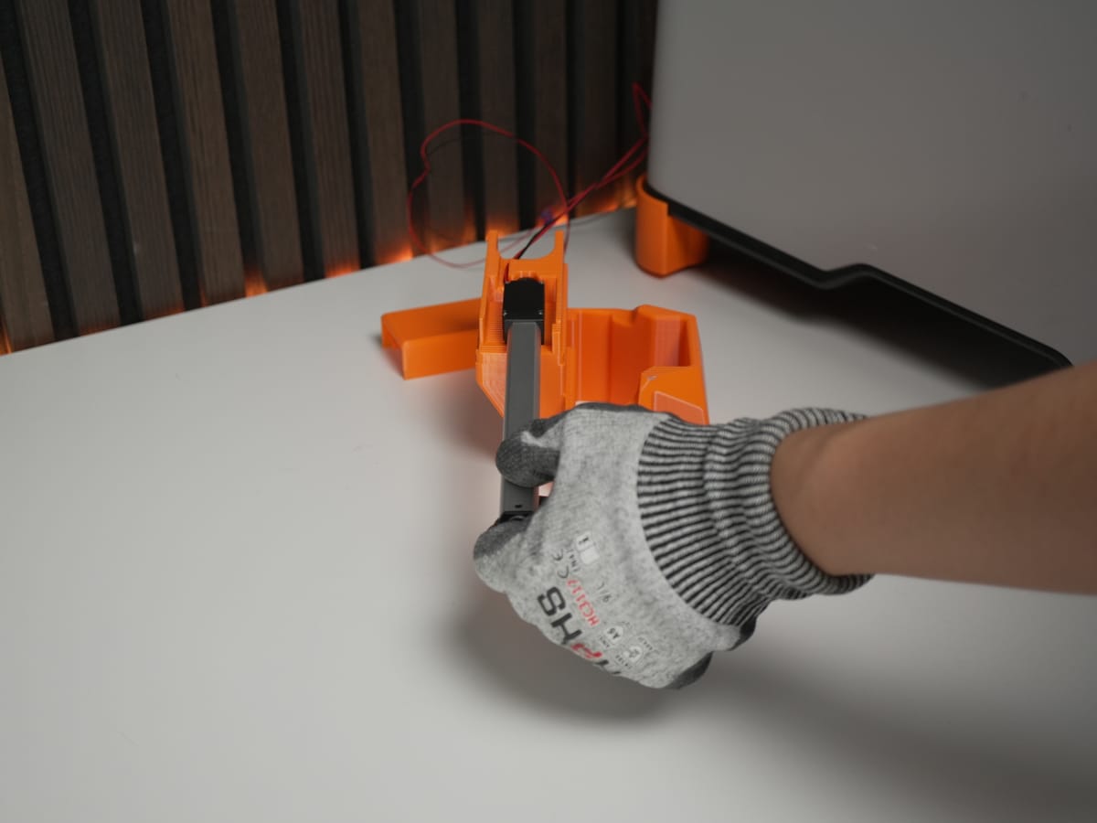
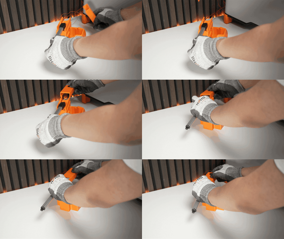
- Slide the actuator into the bottom part until it is fully seated.
- Align the lid with the base and press them together until they click/lock into place.
2. Set up the benders (×2 - repeat for each)
Section titled “2. Set up the benders (×2 - repeat for each)”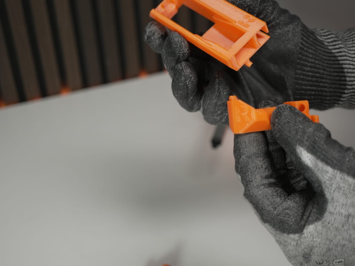
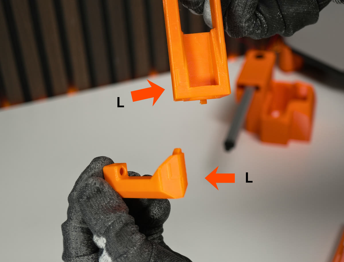
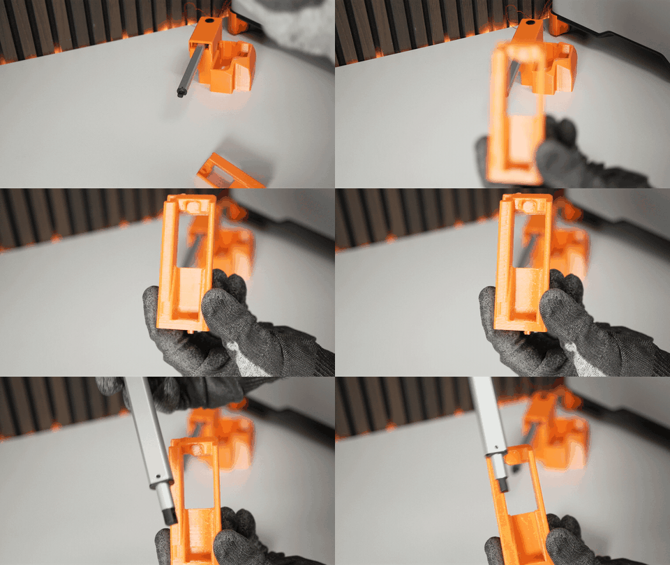
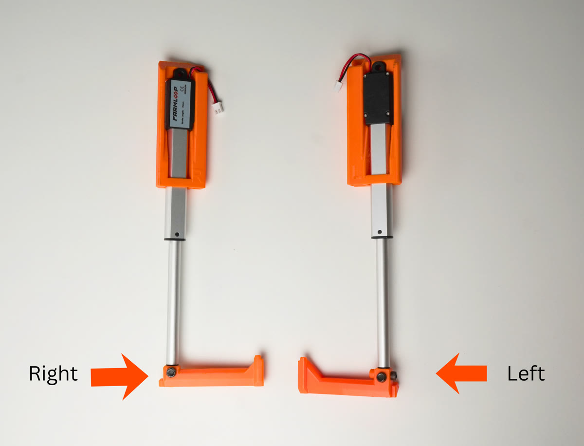
- Slide each actuator into its bender bracket until fully inserted.
- Check that the actuator is facing the correct direction - the cable must sit in the designated gap.
- Attach one hook to each actuator and tighten the screws firmly so the hook does not move.
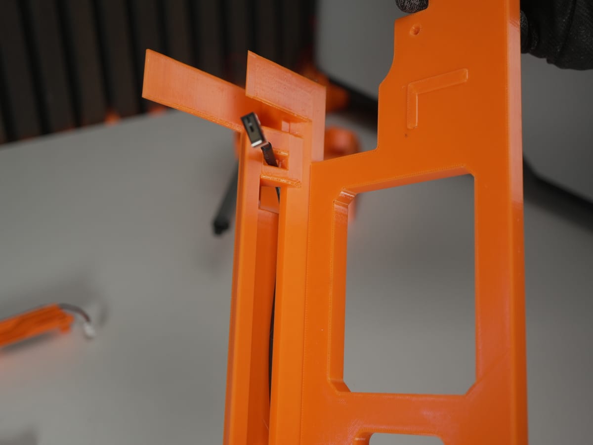
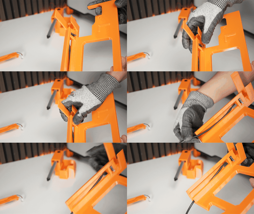
- Press the endstop switch into the slot in the left floor part.
3. Prepare the 3D printer
Section titled “3. Prepare the 3D printer”3.1 Remove the lid
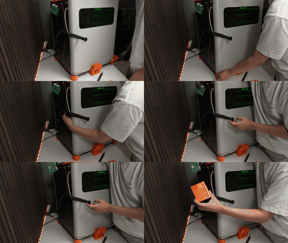
Section titled “3.1 Remove the lid”Remove the printer’s lid and set it aside - you’ll re-fit it at the end.
3.2 Install the scraper on the print head
Section titled “3.2 Install the scraper on the print head”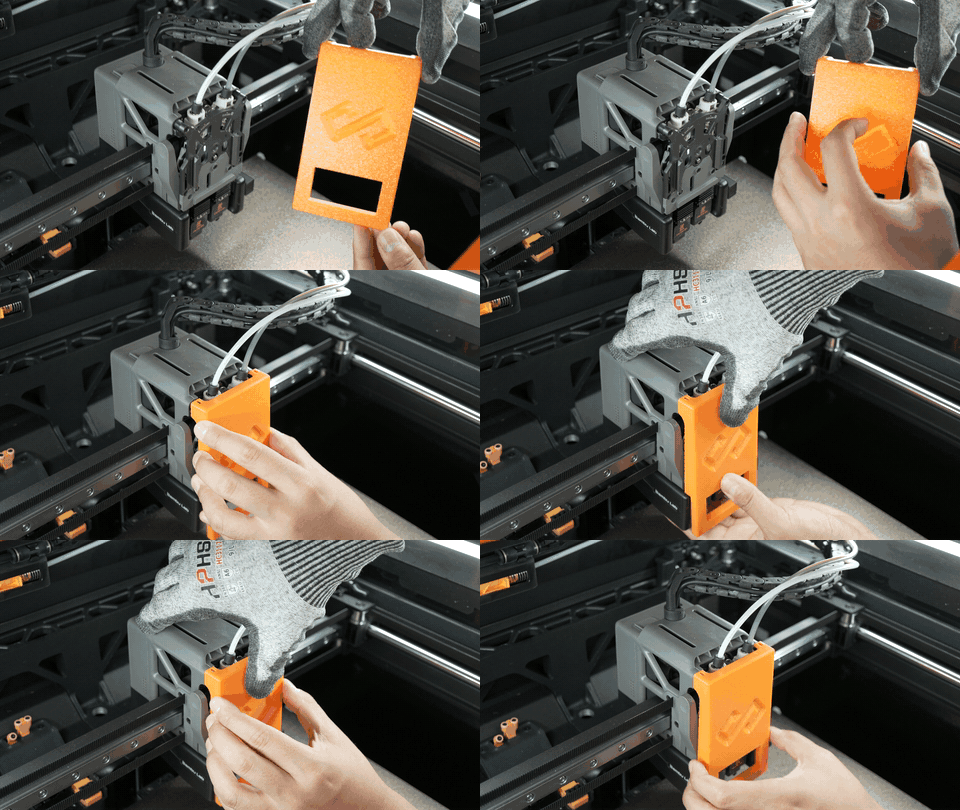
- Remove the original transparent cover from the print head.
- Attach the scraper to the same position.
3.3 Replace the original feet with tilted feet
Section titled “3.3 Replace the original feet with tilted feet”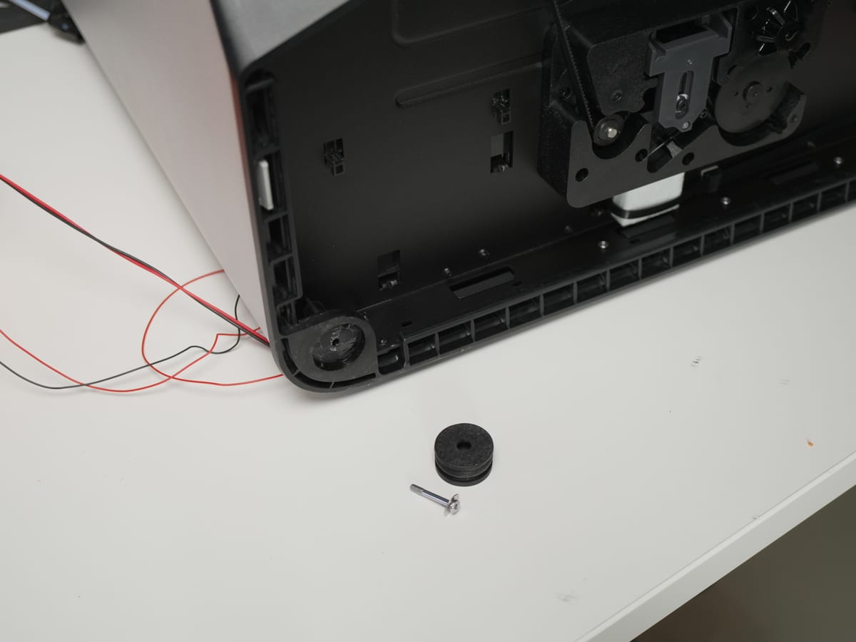
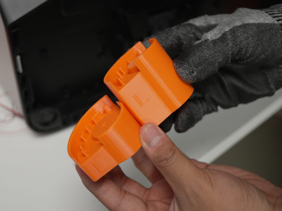
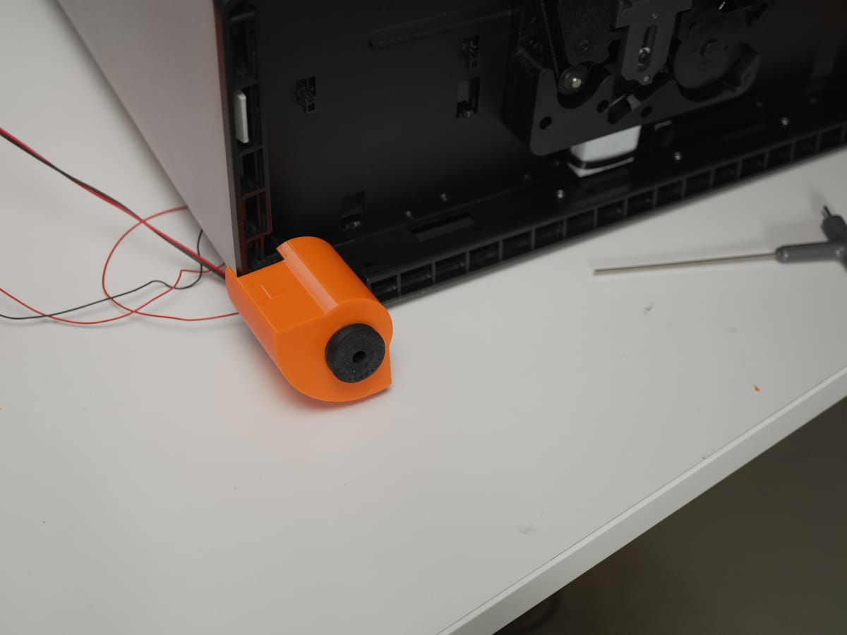
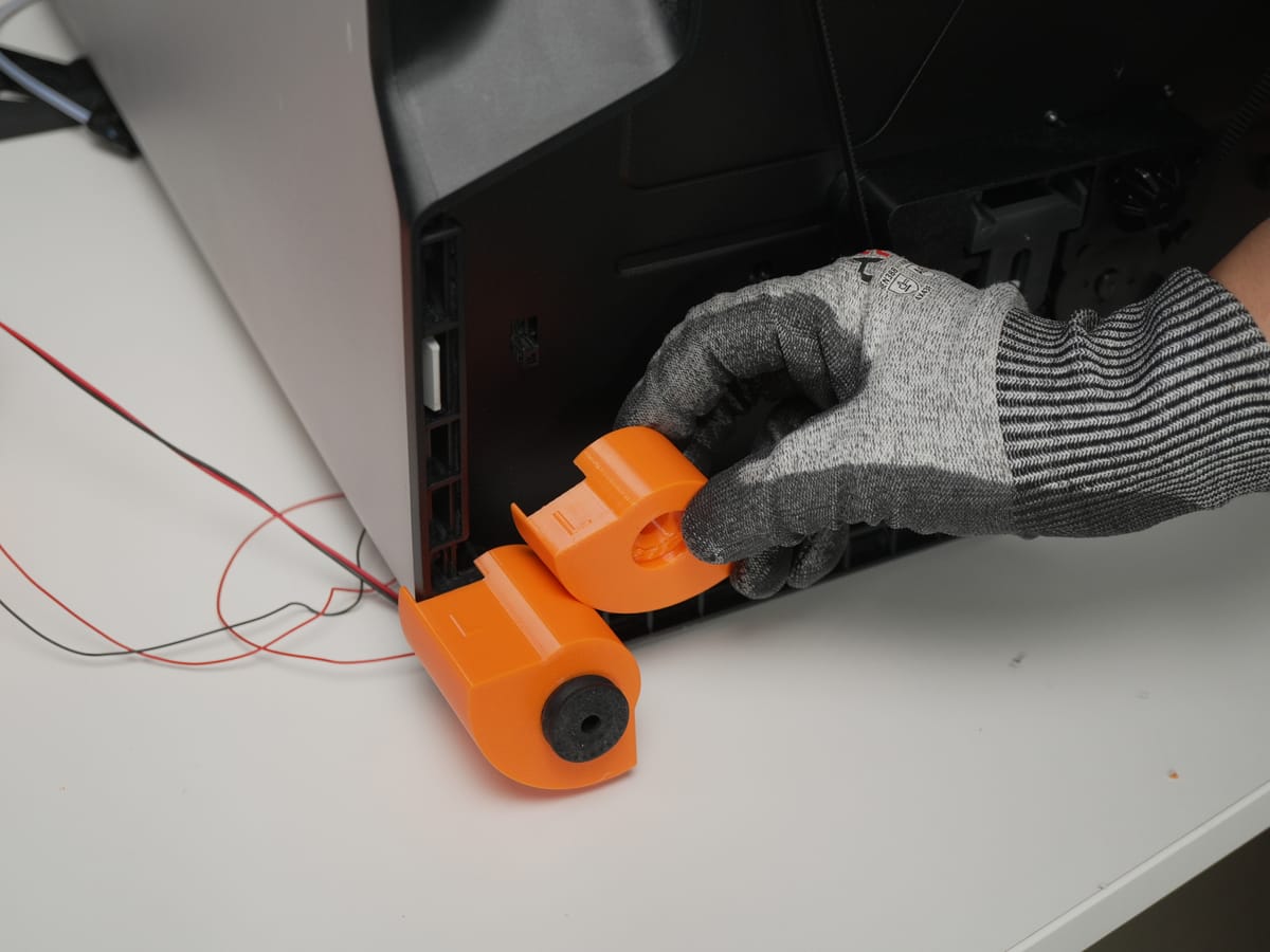
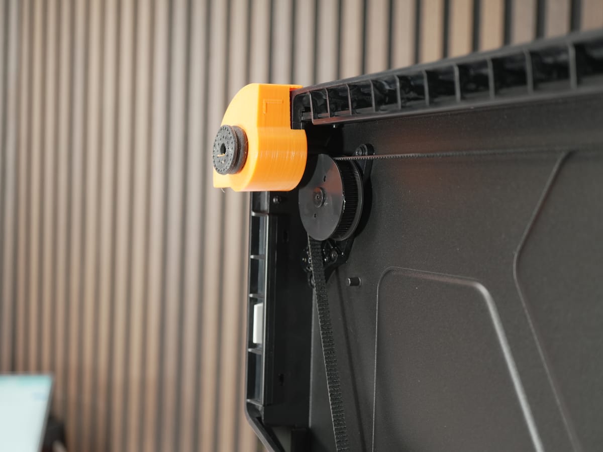
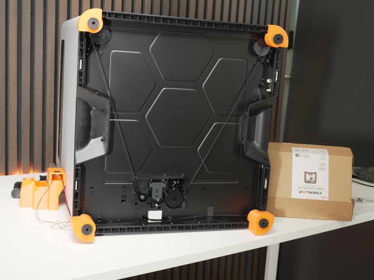
Remove every original foot and replace each one with a tilted foot, screwing it in firmly.
3.4 Swap the door hinge
Section titled “3.4 Swap the door hinge”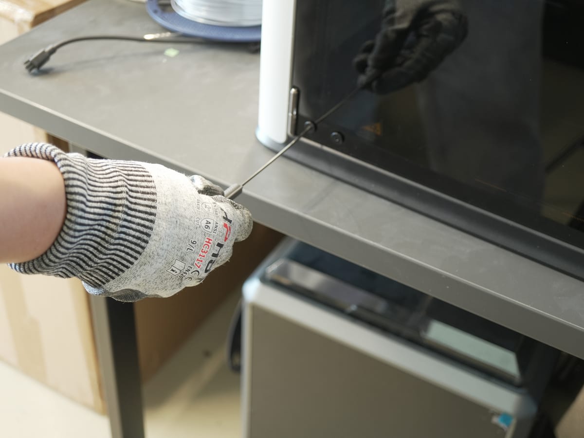
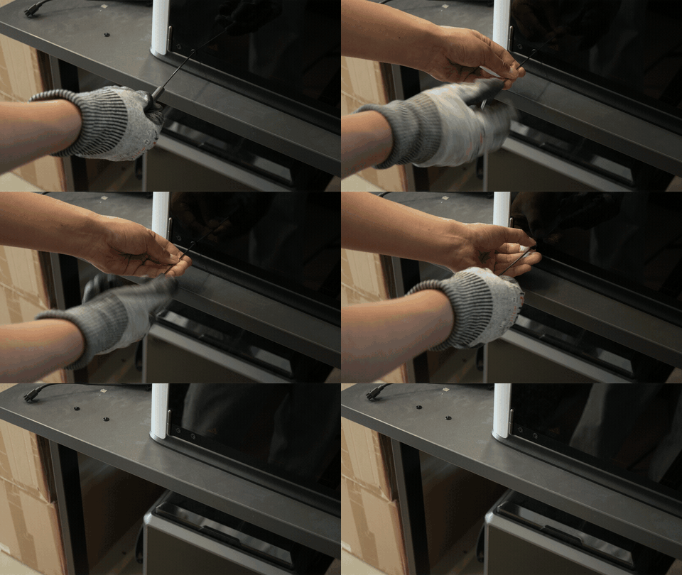
- Remove the bottom two screws from the original door hinge.
- Position the new door hinge in the same place.
- Reinsert the same two screws to secure it.
3.5 Place the lid lifter
Section titled “3.5 Place the lid lifter”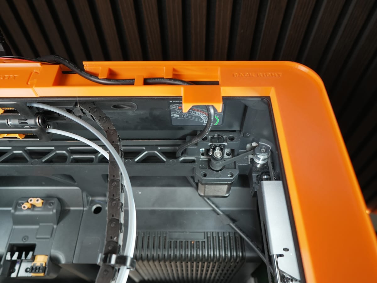
Place the lid lifter into its designated slot. Check the label on the lifter so you fit the correct one for the H2D.
3.6 Route the wire harness into the print room
Section titled “3.6 Route the wire harness into the print room”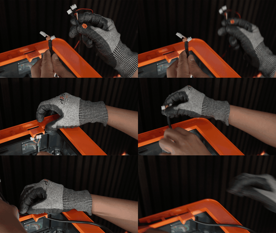
Insert the wire harness into the print room through the designated opening.
3.7 Attach the benders to the print room
Section titled “3.7 Attach the benders to the print room”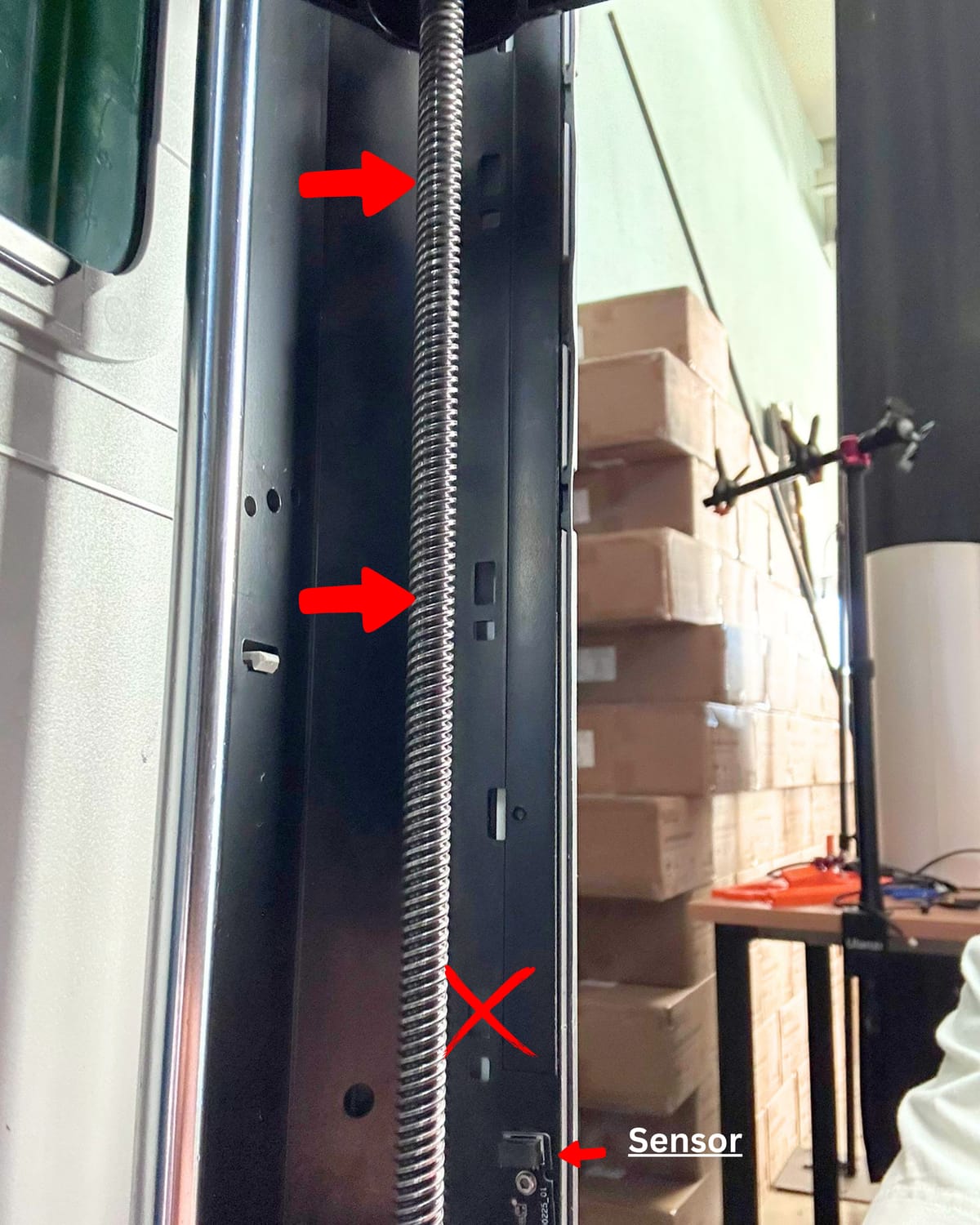
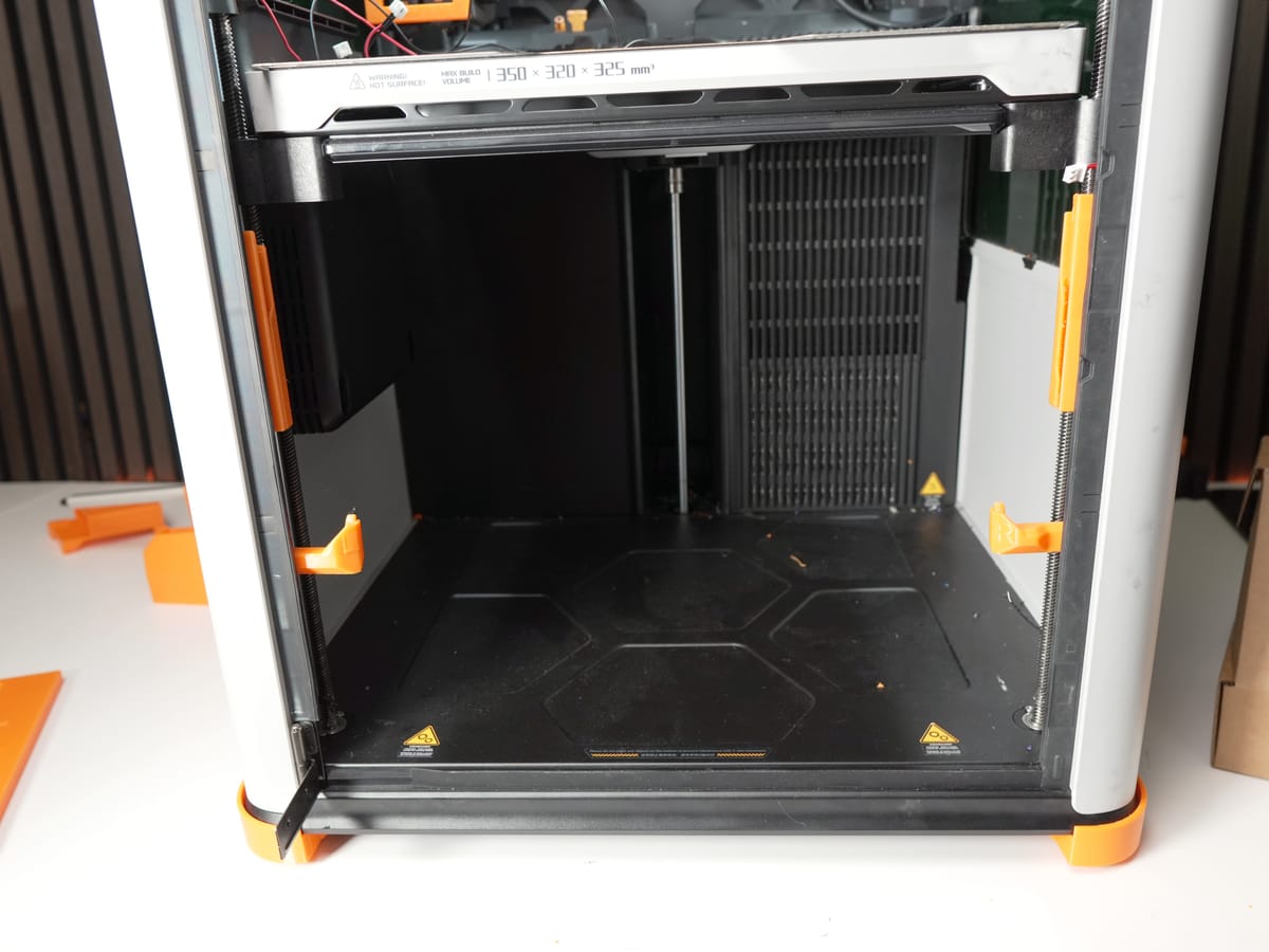
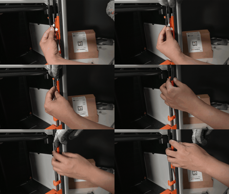
Attach one bender to each side of the print room. Check the direction of the hook before pressing it into place.
3.8 Thread the wire harness through the bottom parts
Section titled “3.8 Thread the wire harness through the bottom parts”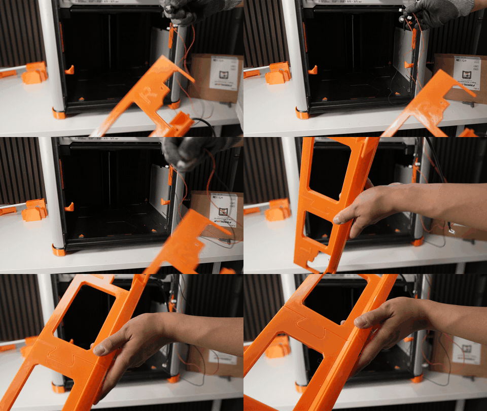
Thread the wire harness through all bottom parts in order, following the intended routing path.
3.9 Connect the actuators to the harness
Section titled “3.9 Connect the actuators to the harness”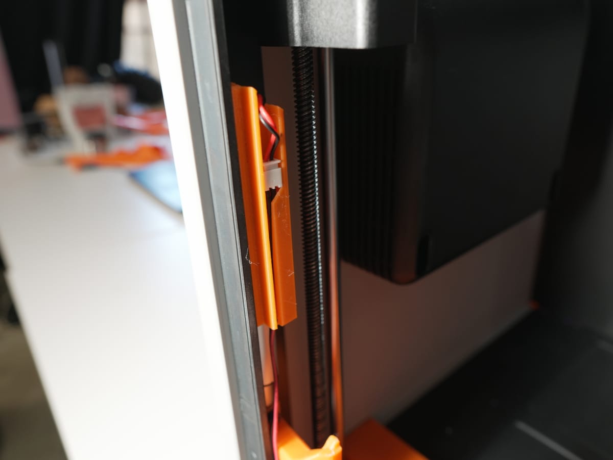
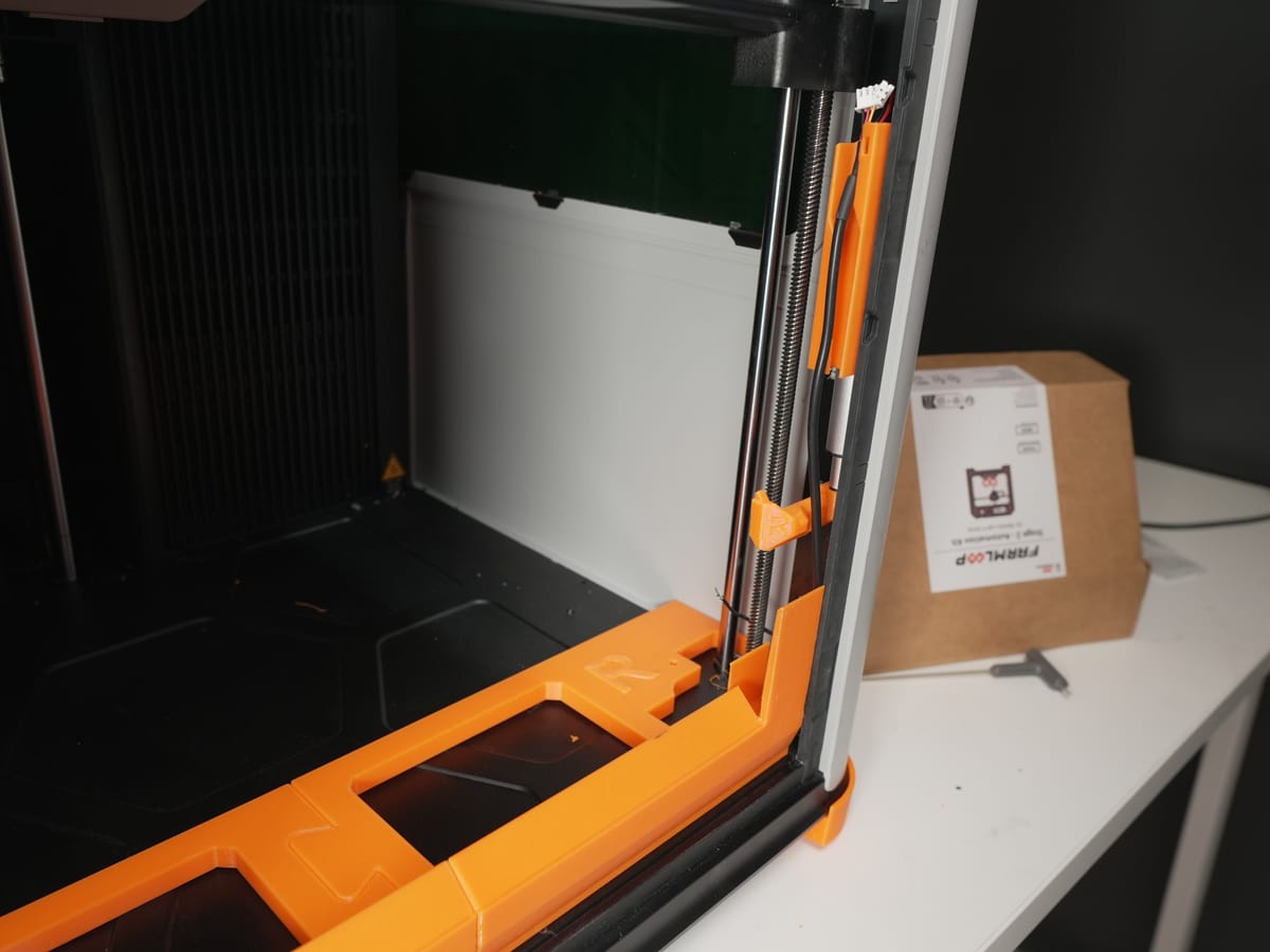
Connect each actuator to its corresponding connector on the wire harness. The Y-cable (V2.1) or orange connector (V3.1) sits between actuator and harness - match it to your board version.
3.10 Screw down the bottom parts
Section titled “3.10 Screw down the bottom parts”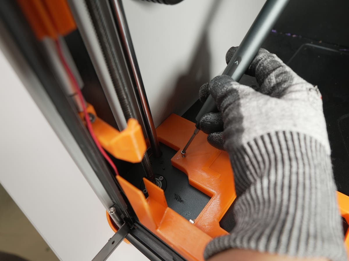
Align the bottom parts with the screw holes on the printer floor and screw them down firmly.
3.11 Route the harness through the side-panel guide
Section titled “3.11 Route the harness through the side-panel guide”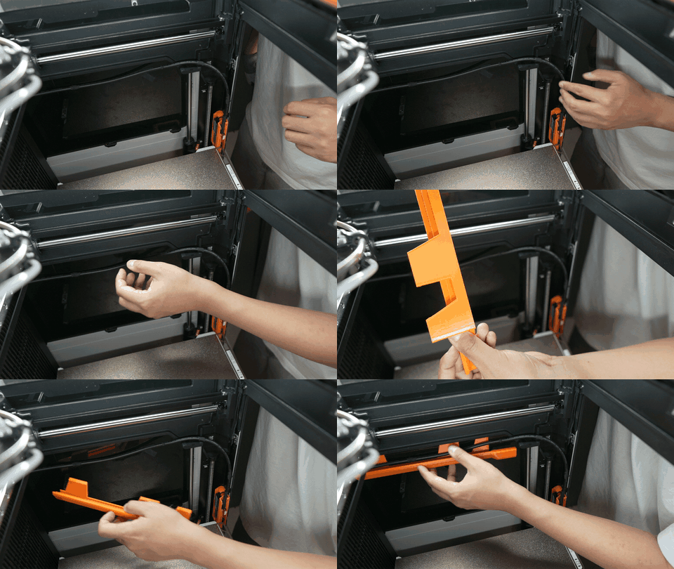
Slide the wire harness guide into the gap between the chassis and the side panel, then route the wire harness through the guide.
3.12 Verify free movement of the print head
Section titled “3.12 Verify free movement of the print head”Adjust the wire harness so it lies flat and tight against the side of the printer. Then manually move the print head to all corners and confirm it moves freely without pulling or snagging the harness.
3.13 Secure the wire harness
Section titled “3.13 Secure the wire harness”Secure the wire harness to the printer frame using tape at regular intervals and zip ties at stress points (where the harness flexes or could snag).
3.14 Install the PCB holder
Section titled “3.14 Install the PCB holder”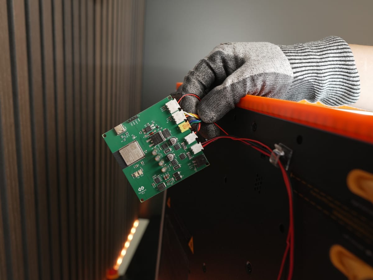
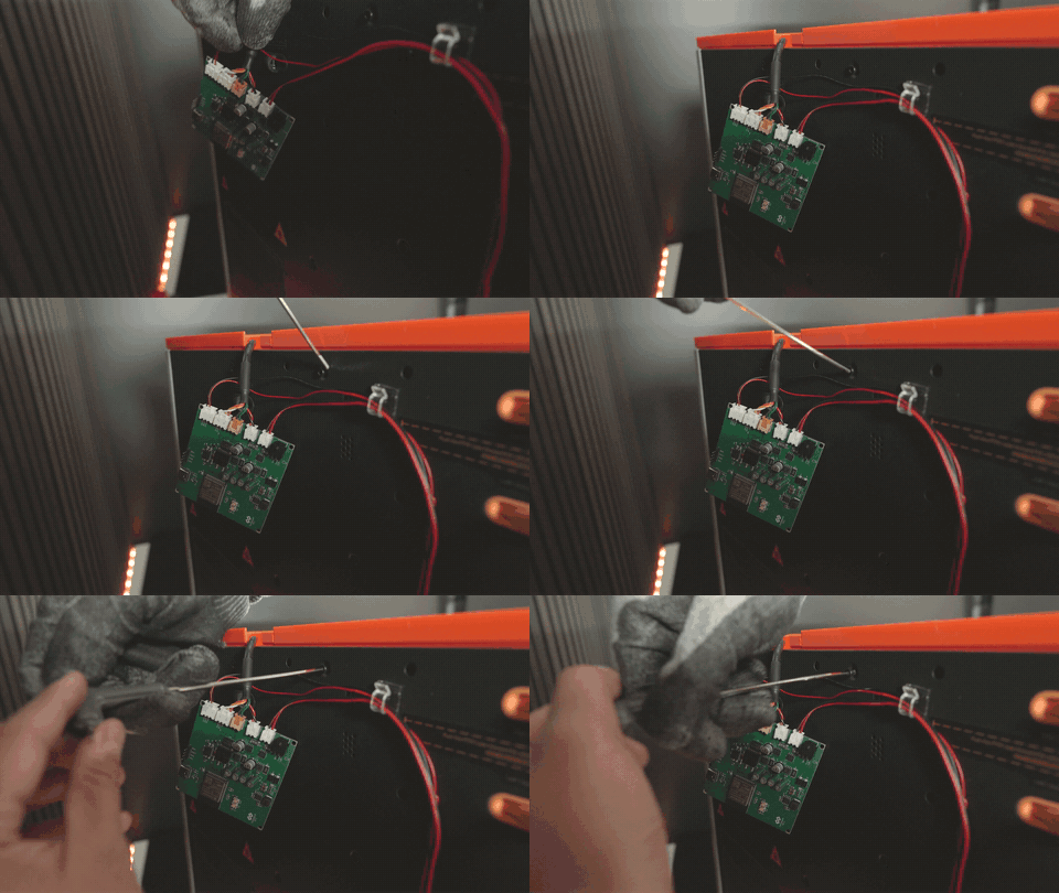
- Remove the top screw from the back panel.
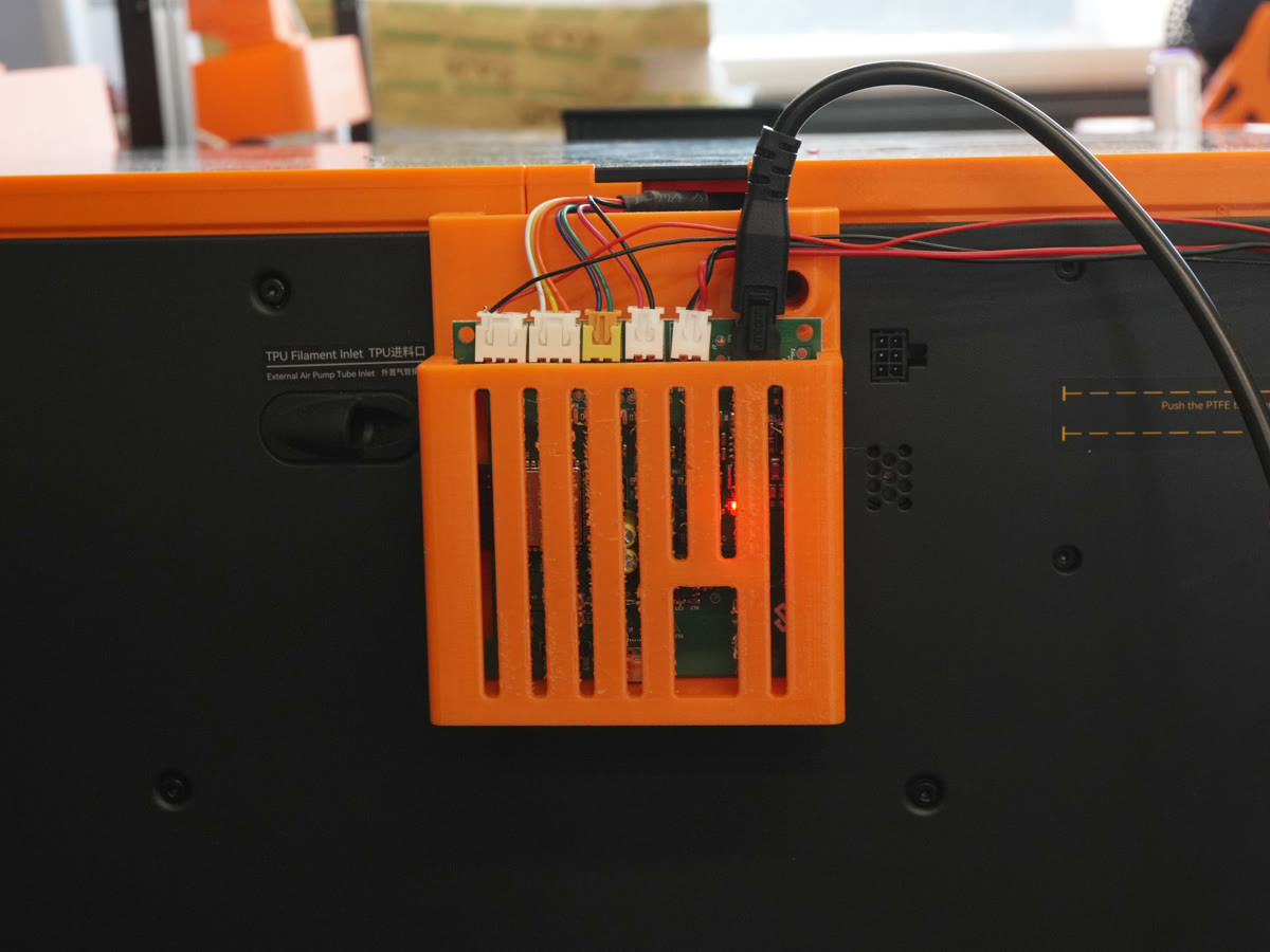
- Position the PCB holder against the panel.
- Reinsert the same screw through the holder to fix it in place.
3.15 Install the door opener
Section titled “3.15 Install the door opener”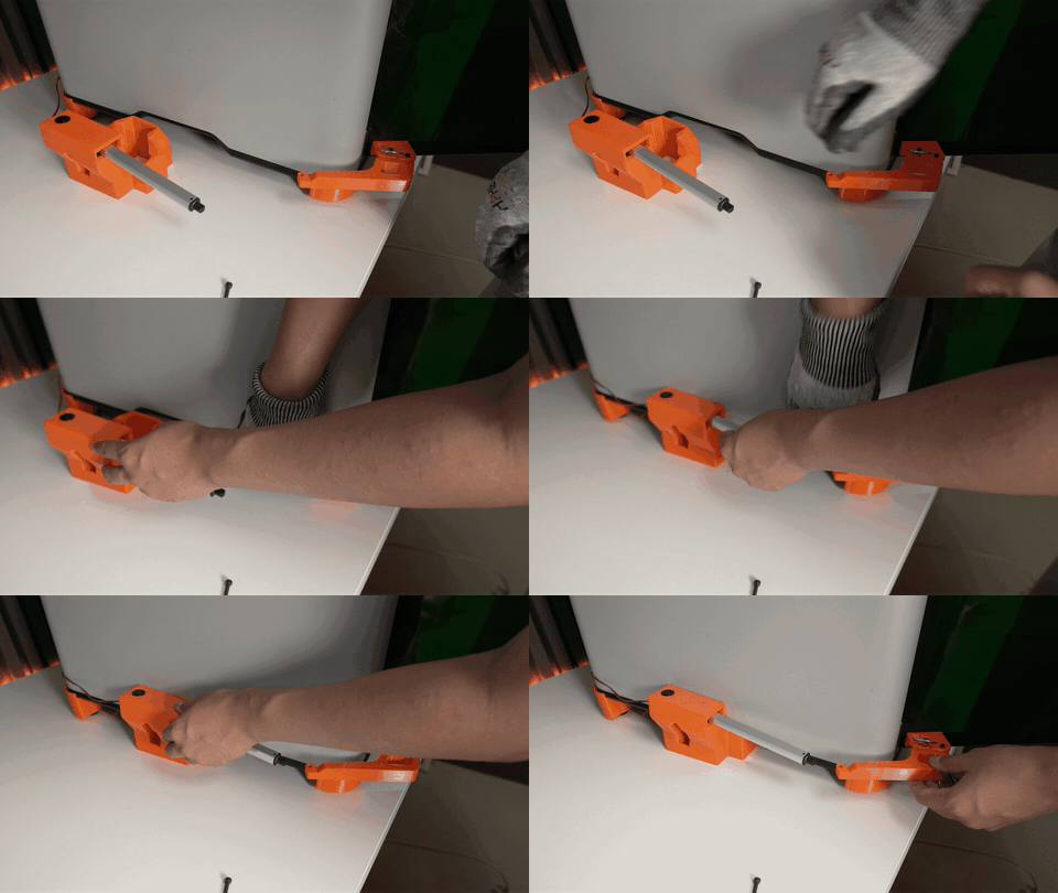
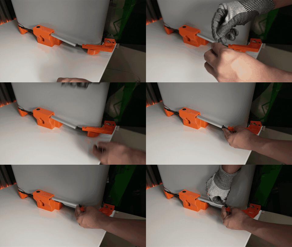
Slide the door opener into the slot at the bottom front of the printer until it sits flush.
3.16 Connect all cables
Section titled “3.16 Connect all cables”Connect every cable. Attach cable clips where needed and press each cable firmly into its clip so nothing dangles or works loose.
3.17 Attach the door opener to the door handle
Section titled “3.17 Attach the door opener to the door handle”
Attach the door opener to the door handle.
3.18 Re-fit the lid + clip the bed
Section titled “3.18 Re-fit the lid + clip the bed”- Place the lid onto the lid lifter.
- Clip the bed using the clips on both sides.
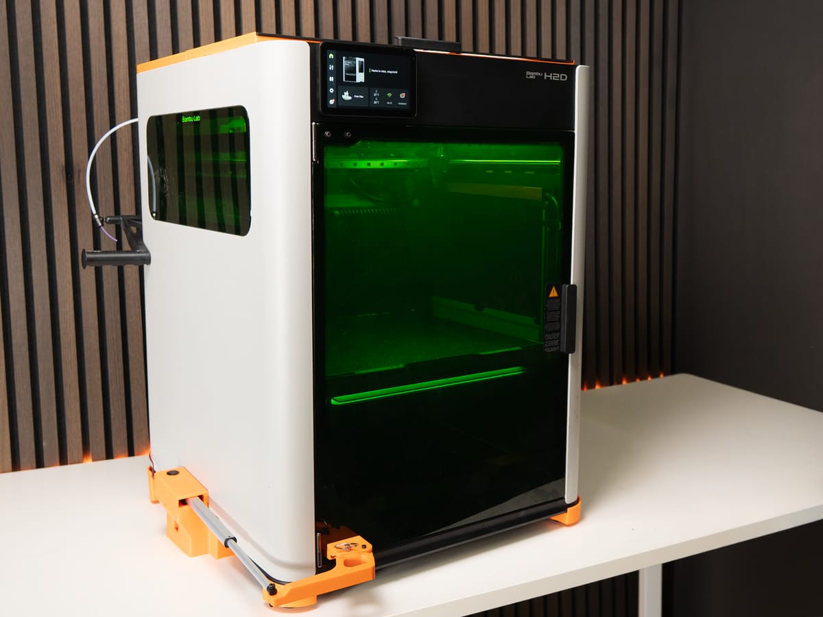
✅ Done!
Next step
Section titled “Next step”Continue the Start here flow at step 3 (firmware update) once your hardware is mounted. After that, run the H series component test to check both benders and the door.
For door-button controls, OTA mode, MQTT setup, and the LED-signal reference, see the sections below - the firmware behaviour is identical to the P / X series.
Operation
Section titled “Operation”Door-button controls
Section titled “Door-button controls”The DOOR BUTTON is the manual-control button on the automatic door console. Its function depends on the current system state:
| System state | Action | Result |
|---|---|---|
| Idle | Short tap | Door control (open/close toggle) |
| Idle | Long press (3+ seconds) | Enter test mode |
| Any state | 5 quick taps within 3 seconds | Enter OTA configuration mode |
| Reset after safety-check failed | Single tap | Recovers from SAFETY_FAILED state. Homes bender, closes door, returns to initial state. |
OTA mode (firmware updates + trigger-mode setup)
Section titled “OTA mode (firmware updates + trigger-mode setup)”OTA is how you flash new firmware and how you wire up the Digital trigger mode (printer IP + LAN access code). The full walkthrough - entering OTA mode, accessing http://farmloop.local, uploading a .bin file - lives on the Accessing the board (OTA mode). Trigger-mode setup is on the Trigger mode page.
LED signals
Section titled “LED signals”After the board boots, the LED shows a sequence indicating connection status.
Successful startup sequence: 3 quick blinks → 5 slow blinks → 10 fast blinks. If you see all three patterns, the board is fully connected to the printer.
During OTA mode: the LED blinks rapidly at 4 Hz continuously until you exit or the timeout is reached.
| LED pattern | Meaning | Action needed |
|---|---|---|
| 3 quick blinks | Boot successful | None, normal |
| 5 slow blinks | Wi-Fi connected | None, good |
| 10 fast blinks | MQTT printer connected | None, fully operational |
| 2 long blinks | Wi-Fi connection failed | Check SSID and password in OTA |
| 4 long blinks | MQTT connection failed | Check printer IP and access code |
Support
Section titled “Support”- Contact: Open a support ticket
- Discord community: included with every FarmLoop account, Lite too: connect your FarmLoop account on the Dashboard to join; Pro and Business members also get the member channels
If your kit arrived damaged, email us with photos and your order number before opening anything further.